
Surface modification control for etch metric enhancement

a surface modification and metric technology, applied in the direction of photomechanical equipment, semiconductor/solid-state device testing/measurement, instruments, etc., can solve the problems of microelectronic device formation, line width, line edges, critical dimension (cd) of patterned features, etc., to reduce the likelihood of pattern collapse for the car

Active Publication Date: 2019-10-15
TOKYO ELECTRON LTD
View PDF85 Cites 15 Cited by
  • Summary
  • Abstract
  • Description
  • Claims
  • Application Information

AI Technical Summary

Benefits of technology

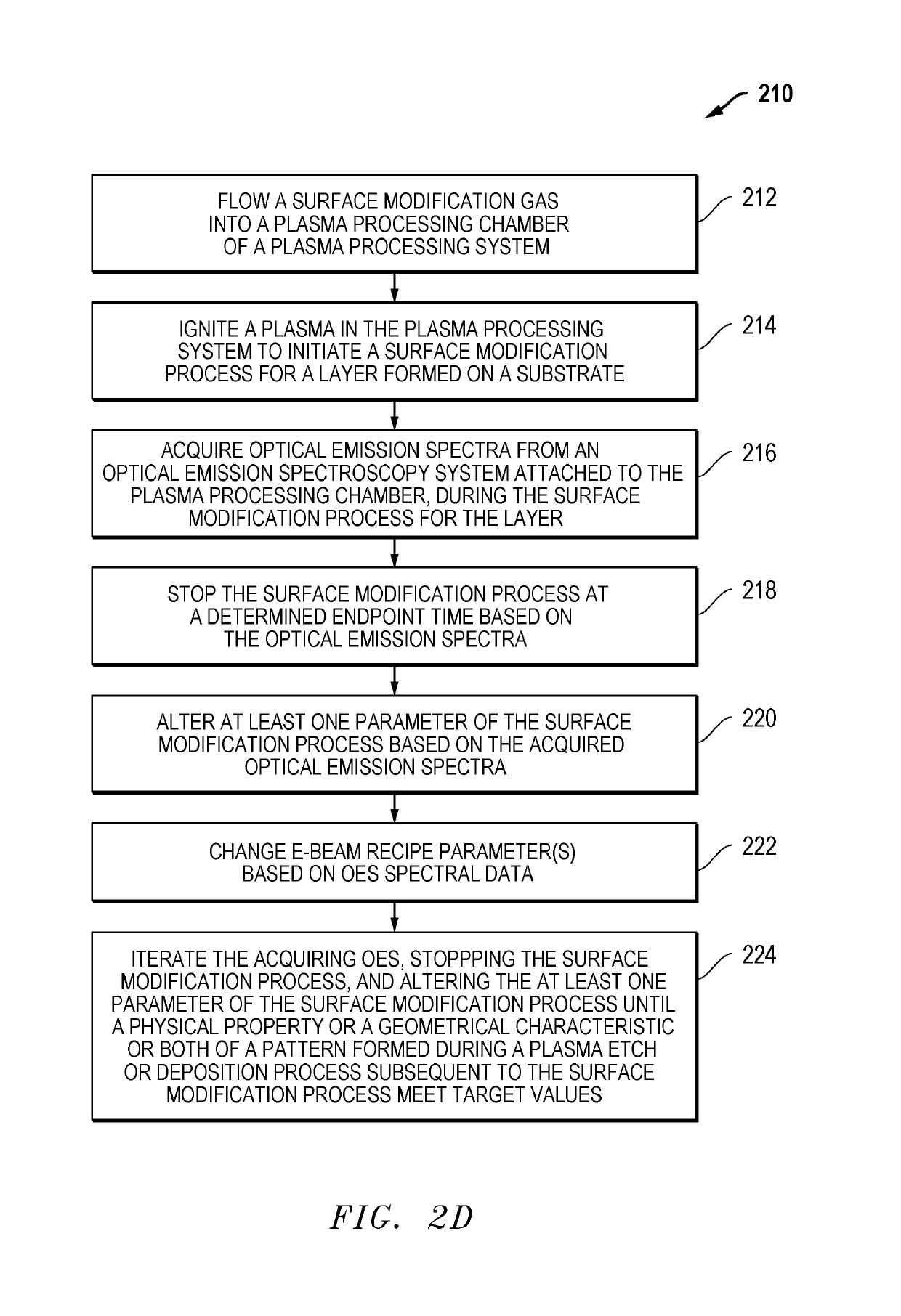
[0020]In an additional embodiment, the layer formed on the substrate includes a chemically amplified resist (CAR), and the method also includes altering at least one parameter of the surface modification process based on the acquired optical emission spectra to reduce likelihood of pattern collapse for the CAR. In a further embodiment, the CAR comprises an ArF-based dry or immersion resist.

Problems solved by technology

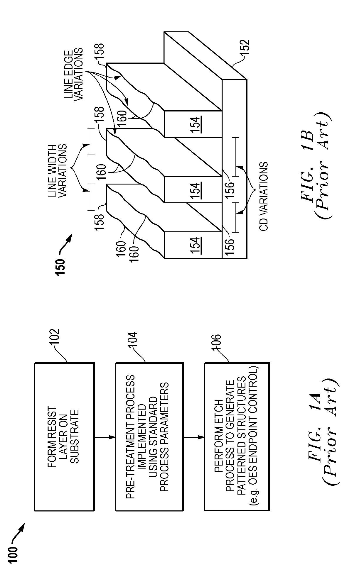
However, even with more precise endpoint control, etch processes can still lead to undesirable variations in line width, line edges, and critical dimension (CD) of patterned features formed during the etch process.
Variations within the line structures 154 can lead to subsequent problems with microelectronic devices formed with respect to the substrate 152.

Method used


Image

  • Surface modification control for etch metric enhancement
  • Surface modification control for etch metric enhancement
  • Surface modification control for etch metric enhancement

Examples


Embodiment Construction

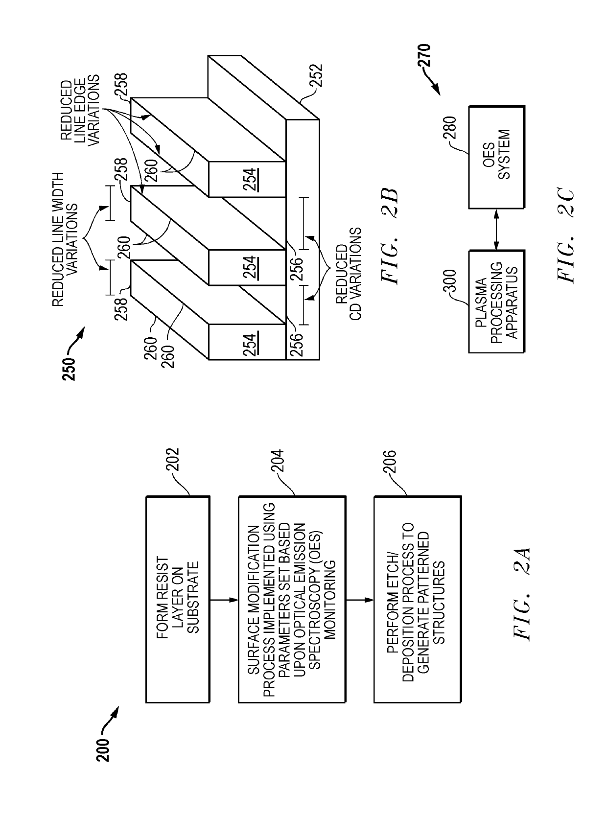
[0046]A method is disclosed for monitoring and controlling a process of plasma-assisted surface modification of a layer formed on a substrate. The method includes flowing a surface modification gas into a plasma processing chamber of a plasma processing system, igniting a plasma in the plasma processing chamber to initiate a surface modification process for a layer formed on a substrate, and acquiring optical emission spectra from an optical emission spectroscopy system attached to the plasma processing chamber, during the surface modification process for the layer. For one embodiment, the method also includes altering at least one parameter of the surface modification process based on the acquired optical emission spectra. For one embodiment, the acquired optical emission spectra can include an intensity of a spectral line, a slope of a spectral line, or both. The surface modification process could comprise a high-density electron exposure or ultraviolet light-based treatment of on...


PUM

PropertyMeasurementUnit
wavelengthaaaaaaaaaa
frequencyaaaaaaaaaa

Abstract

A method is disclosed for monitoring and controlling a process of plasma-assisted surface modification of a layer formed on a substrate. The method includes flowing a surface modification gas into a plasma processing chamber of a plasma processing system, igniting a plasma in the plasma processing chamber to initiate a surface modification process for a layer formed on a substrate, and acquiring optical emission spectra from an optical emission spectroscopy system attached to the plasma processing chamber, during the surface modification process for the layer. For one embodiment, the method includes altering at least one parameter of the surface modification process based on the acquired optical emission spectra. For one embodiment, the acquired optical emission spectra can include an intensity of a spectral line, a slope of a spectral line, or both to enable endpoint control of the surface modification process. Additional methods and related systems are also disclosed.

Description

RELATED APPLICATIONS[0001]This application claims priority to the following co-pending provisional application: U.S. Provisional Patent Application Ser. No. 62 / 473,193, filed Mar. 17, 2017, and entitled “SURFACE MODIFICATION CONTROL FOR ETCH METRIC ENHANCEMENT,” which is hereby incorporated by reference in its entirety.BACKGROUND OF THE INVENTION[0002]Optical emission spectroscopy (OES) spectra have been used for plasma dry etch processes to determine an etch endpoint. For example, when an etch process passes through a first material layer into a second material layer having different component materials, a sudden change in the OES spectral content can often be seen. This sudden change can be used as an etch endpoint indicator. Identifying a proper etch endpoint helps to control the amount of etching that occurs into stop layers during the etch process. However, even with more precise endpoint control, etch processes can still lead to undesirable variations in line width, line edges...

Claims


Application Information

Patent Timeline
Patent Type & Authority Patents(United States)
IPC IPC(8): H01L21/66H01L21/311H01J37/32H01L21/027G03F7/20G03F7/40
CPCH01J37/32935H01J37/32972H01L21/0273H01L21/31144H01L21/31116H01L21/3065H01J37/32174H01L22/12H01L21/67276H01L21/67253H01L22/26G03F7/2024G03F7/40
Inventor COPPA, BRIAN J.PUROHIT, VISWASWATANABE, SEIICHIKOMATSU, KENJI
Owner TOKYO ELECTRON LTD
Learn More