Endoscope

a technology of endoscopes and endoscopes, applied in the field of endoscopes, can solve the problems of increased length of cables connected to image communication devices, poor workability, and increased space for processing extra length, and achieve the effect of convenient assembly, repair and maintenan

Active Publication Date: 2019-11-05
FUJIFILM CORP
View PDF13 Cites 0 Cited by
  • Summary
  • Abstract
  • Description
  • Claims
  • Application Information

AI Technical Summary

Benefits of technology

[0010]For this reason, at the time of assembly or repair of the first connector of the endoscope, it is necessary to work in a state accessible to the relay board and the cables from the devices and the universal cord. At the time of working in a state where the relay board is completely exposed, that is, when the relay board is taken out to the outside from the first connector, the cables from the devices and the universal cord need to have extra length. Therefore, it is necessary to work while paying attention to the extra length of all cables when returning the relay board to the first connector. For this reason, workability is poor, and space for processing the extra length is required. In addition, since the length of a cable connected to an image communication device is increased, noise is easily generated.
[0012]The invention has been made in view of such a situation, and it is an object of the present invention to provide an endoscope which can perform non-contact electric power supply and non-contact signal transmission and whose assembly, repair, and maintenance are easy.
[0024]According to the invention, it is possible to perform non-contact electric power supply and non-contact signal transmission and to easily perform assembly, repair, and maintenance.

Problems solved by technology

For this reason, workability is poor, and space for processing the extra length is required.
In addition, since the length of a cable connected to an image communication device is increased, noise is easily generated.

Method used


Image

  • Endoscope
  • Endoscope
  • Endoscope

Examples


Embodiment Construction

[0032]Hereinafter, a preferred embodiment of the invention will be described with reference to the accompanying diagrams. The invention will be described by way of the following preferred embodiment. It is possible to make changes through a number of techniques without departing from the scope of the present invention, and it is possible to use embodiments other than the present embodiment. Accordingly, all changes within the range of the invention are included in the range of the invention.

[0033]Here, portions denoted by the same reference numerals in diagrams are the same elements having the same functions. In this specification, when a numerical range is expressed using “˜”, the values of the upper and lower limits indicated by “˜” are assumed to be included in the numerical range.

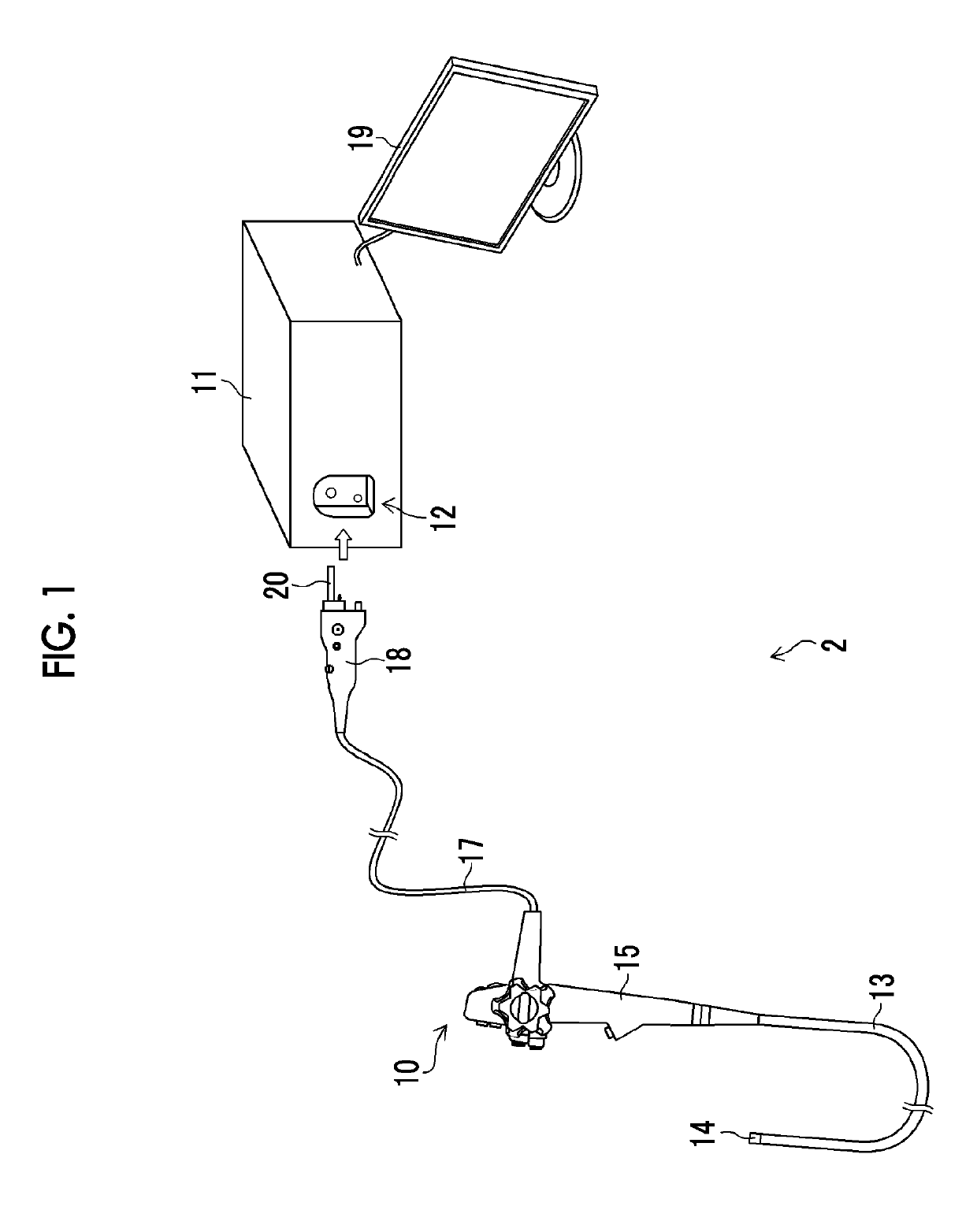
[0034]FIG. 1 is an external view showing an endoscope system to which the invention is applied.

[0035]As shown in FIG. 1, an endoscope system 2 includes an endoscope 10 and an endoscope processor device ...


PUM


Abstract

There is provided an endoscope which can perform non-contact electric power supply and non-contact signal transmission and of which assembly, repair, and maintenance can be easily performed. A power receiving unit, an image signal transmission unit, and an endoscope side signal transmission and reception unit are disposed in the space (hollow structure) of a first connector of an endoscope. The first connector of the endoscope includes a first connector case and a second connector case disposed in order from a side of the second connector, and a division line between the first and second connector cases includes an inclined portion that is inclined with respect to an insertion direction of the first and second connectors.

Description

CROSS-REFERENCE TO RELATED APPLICATIONS[0001]The present application claims priority under 35 U.S.C. § 119 to Japanese Patent Application No. 2014-198946, filed on Sep. 29, 2014. The above application is hereby expressly incorporated by reference, in its entirety, into the present application.BACKGROUND OF THE INVENTION[0002]1. Field of the Invention[0003]The present invention relates to an endoscope.[0004]2. Description of the Related Art[0005]An endoscope system is configured to include an endoscope and an endoscope processor device. The endoscope includes an image pick-up unit, such as a charge coupled device (CCD) image sensor to image the inside of a body cavity, and a first connector provided at the end of a universal cord. The endoscope processor device includes a second connector to which the first connector of the endoscope is detachably connected, a control unit for performing image processing and the like on image data output from the endoscope, and a light source. In the...

Claims


Application Information

Patent Timeline
Patent Type & Authority Patents(United States)
IPC IPC(8): A61B1/00A61B1/015
CPCA61B1/00121A61B1/00016A61B1/015A61B1/00114A61B1/00112A61B1/00029A61B1/00013
Inventor HARA, KAZUYOSHI
Owner FUJIFILM CORP
Why Eureka
Try Eureka