Chassis for vehicle

a vehicle and chassis technology, applied in the field of chassis for vehicles, can solve the problems of difficult manoeuvrability of wheelchairs, difficulty in maneuvering wheelchairs, front wheels may have problems of getting stuck in loose surfaces, etc., and achieve the effects of improving driving distance, manoeuvrability, weight, volume, and ability to climb obstacles

Active Publication Date: 2019-11-12
BENDT IPR APS
View PDF29 Cites 0 Cited by
  • Summary
  • Abstract
  • Description
  • Claims
  • Application Information

AI Technical Summary

Benefits of technology

[0011]The present invention provides a chassis for vehicle with improvements related to driving distance, manoeuvrability, weight, volume, complexity, and ability to climb obstacles.
[0012]The presently disclosed invention relates to a chassis for vehicle, comprising: a rigid frame, a pair of side wheels in a parallel configuration, a steerable front wheel, a steerable rear wheel, at least one electric motor, wherein at least one of said front wheel or rear wheel is connected to and driven by the at least one electric motor, the chassis characterized in that said front and rear wheels are mutually connected through a turning mechanism arranged to turn said front and rear wheels simultaneously and synchronously between: a middle position in which the axles of the front and rear wheels are substantially parallel with the axles of the side wheels, and left or right end positions, in which the axles of the front and rear wheels are substantially perpendicular to the axles of the side wheels. In this configuration the energy that the motor(s) has / have to supply is only applied to propulsion directly in the moving direction. This is a more energy efficient solution, which means that a vehicle mounted on the chassis can be transported a longer distance on the same battery compared to a conventional chassis. The fact that the front and rear wheels are connected through a turning mechanism arranged to turn said front and rear wheels simultaneously and synchronously makes the design simple and efficient compared to having individually controlled steering mechanisms for the front wheel and rear wheel. If the front and rear wheels are positioned with the same distance from the axis of the parallel side wheels, it means that the wheels have the same turning angles (but opposite) when turning, which is beneficial for the simplicity of the steering construction, and also implies that the front and rear wheels will have the same rotation speed. An additional advantage of the presently disclosed chassis in relation to a solution where the parallel side wheels provide the propulsion is that the front and rear wheel may be positioned 90° in relation to the parallel side wheels, which provides for a smaller turning radius.
[0013]Further advantages of the presently disclosed inventions relate to at least one of the side wheels being tiltable relative to a horizontal plane, which improves the ability to climb obstacles when driving. In one embodiment the rigid frame comprises two parts connected to each other in a substantially horizontal plane. In such a solution one part may be arranged in a substantially longitudinal direction of the chassis and connected to the front wheel, rear wheel and one of the side wheel, whereas the other part is connected to the other side wheel. The second part may be vertically tiltable in relation to the first part, thereby allowing improved ability to climb obstacles. Furthermore, if all parts of the chassis are arranged in substantially one horizontal plane, the height of the chassis is only as high as the diameter of the wheels.
[0014]In one embodiment the rear wheel is connected to and driven by a primary electric motor. In another embodiment of the invention the rear wheel is connected to and driven by a primary electric motor and the front wheel is connected to and driven by a secondary electric motor. By having the electric motor(s) for each wheel can be seen as a means to further simplify the design and avoid additional wiring.

Problems solved by technology

Since the beginning of the development of driving frames for electrically driven vehicles, it has been a known problem to ensure 1) adequately long possible driving distance; 2) adequately large manoeuvrability; 3) adequately low weight; 4) adequately minimum appearance; 5) adequately minimum complexity; and 6) adequate capacity to overcome obstacles.
They have relatively large turning radius, and the fact that they turn by regulating rotation speed of the two parallel wheels individually makes them energy inefficient since turning implies that the rotation speed of one or both of the wheels is changed.
As a consequence, larger batteries are needed, which makes the wheelchair difficult to manoeuvre.
For example, the chassis having the two parallel, not steerable wheels placed at the rear part of the chassis may have problems driving down sloping surfaces, and the front wheels may have problems of getting stuck in loose surfaces because of surface pressure from size and weight distribution.
If the two parallel, not steerable wheels are instead placed at the front part of the chassis, there is a risk of the wheelchair tilting forward when driving downwards on sloping surfaces or having problems when driving upwards on sloping surfaces.
A known disadvantage with this chassis is the large turning radius due to the driving force in a forward direction of the vehicle, i.e. the rear wheel do not propel in the direction of the steering wheel.
A further disadvantage is that if the front wheel would be turned 90° in relation to the rear wheel, the wheelchair would not drive and would risk tipping over.
These chassis are characterized by a poor ability to climb differences in level, and increased installation height because of the rotary shaft above the driving wheel for steering, typically resulting in smaller wheels as a trade-off.
The abovementioned solutions seek to solve various problems concerning chassis for vehicles, but they all have problems with regard to the combination of the following aspects: driving distance, manoeuvrability, weight, size, steering complexity, and ability to climb obstacles.

Method used


Image

  • Chassis for vehicle
  • Chassis for vehicle
  • Chassis for vehicle

Examples


Embodiment Construction

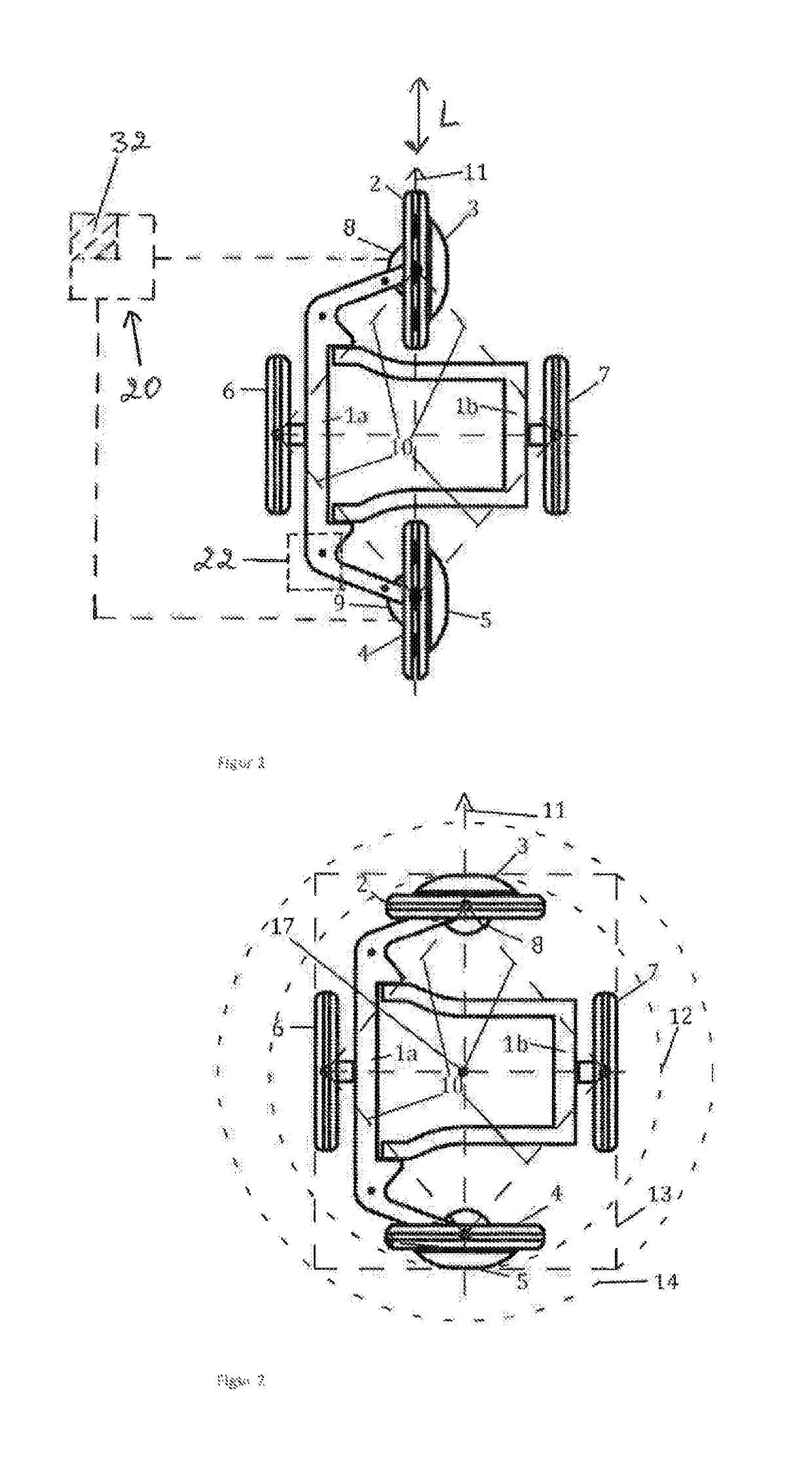
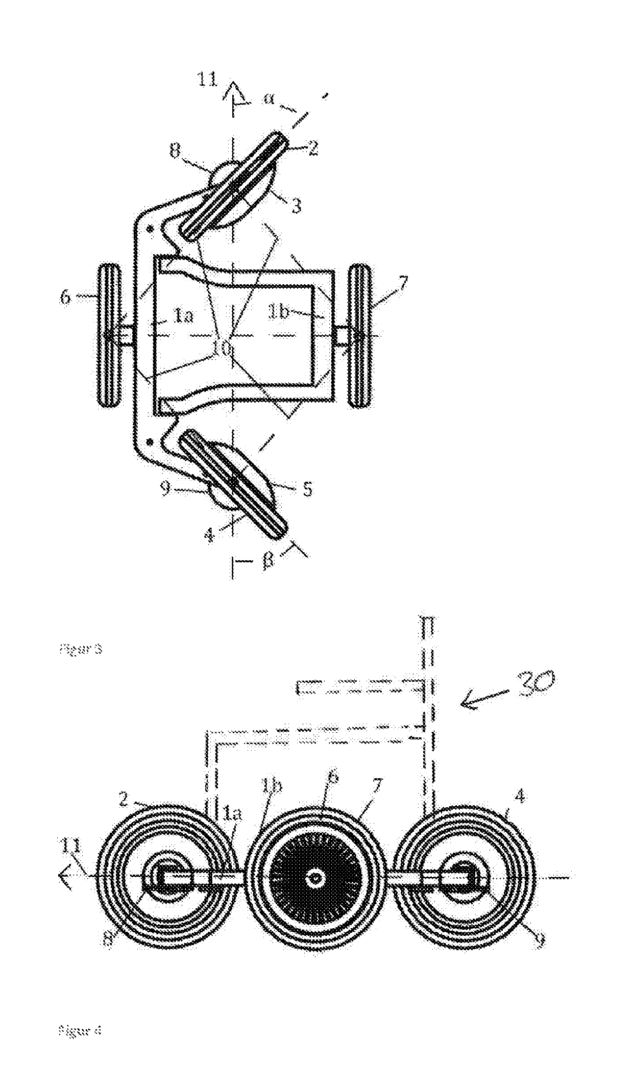
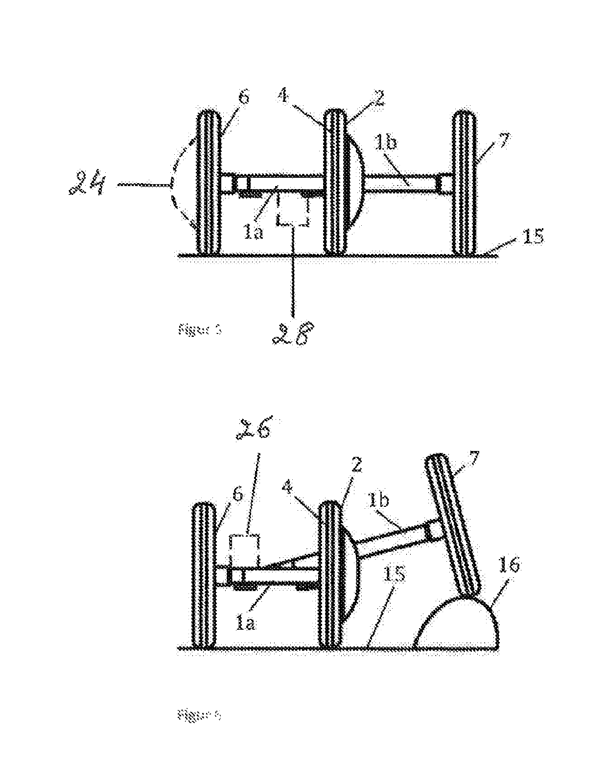
[0022]The presently disclosed invention relates to a chassis for vehicle, comprising: a rigid frame, a pair of side wheels in a parallel configuration, a steerable front wheel, a steerable rear wheel, at least one electric motor, wherein at least one of said front wheel or rear wheel is connected to and driven by the at least one electric motor, the chassis characterized in that said front and rear wheels are mutually connected through a turning mechanism arranged to turn said front and rear wheels simultaneously and synchronously between: a middle position in which the axles of the front and rear wheels are substantially parallel with the axles of the side wheels, and left or right end positions, in which the axles of the front and rear wheels are substantially perpendicular to the axles of the side wheels.

[0023]The rigid frame may be an asymmetric construction about a longitudinal axis L in the forward direction 11 of the chassis in such an embodiment said rigid frame constitutes ...


PUM


Abstract

The present invention relates to a chassis for vehicle, comprising: a rigid frame, a pair of side wheels in a parallel configuration, a steerable front wheel, a steerable rear wheel, at least one electric motor, wherein at least one of said front wheel or rear wheel is connected to and driven by the at least one electric motor, and wherein said front and rear wheels are mutually connected through a turning mechanism arranged to turn said front and rear wheels simultaneously and synchronously between a middle position in which the axles of the front and rear wheels are substantially parallel with the axles of side wheels, and left or right positions, in which the axles of the front and rear wheels are substantially perpendicular to the axles of the side wheels.

Description

FIELD OF INVENTION[0001]The invention relates to a chassis for vehicle having a steerable front wheel and a steerable rear wheel. The invention further relates to a vehicle, such as a wheelchair, comprising the chassis.BACKGROUND OF INVENTION[0002]Since the beginning of the development of driving frames for electrically driven vehicles, it has been a known problem to ensure 1) adequately long possible driving distance; 2) adequately large manoeuvrability; 3) adequately low weight; 4) adequately minimum appearance; 5) adequately minimum complexity; and 6) adequate capacity to overcome obstacles. These problems have not been seen to have been solved in one invention.[0003]A chassis constitutes a structural part or parts of an electrically driven wheelchair. Wheelchairs are often used in buildings, means of transportation and other places where there may be a limited turning space, but also outdoors where there are requirements to be able to overcome obstacles in the form of kerbstones...

Claims


Application Information

Patent Timeline
Patent Type & Authority Patents(United States)
IPC IPC(8): A61G5/04A61G5/06A61G5/10B60K1/02B60K7/00
CPCB60K7/0007A61G5/06B60K1/02A61G5/1051A61G5/10A61G5/1089A61G5/04Y02T10/7258B60K2007/0038Y02T10/72
Inventor BENDT, MADS
Owner BENDT IPR APS
Why Eureka
Try Eureka