
Catalyst tube for reforming

Active Publication Date: 2019-11-12
TECH FRANCE SA
View PDF15 Cites 4 Cited by
  • Summary
  • Abstract
  • Description
  • Claims
  • Application Information

AI Technical Summary

Benefits of technology

The invention provides a catalyst tube configuration that allows for easy replacement of the catalyst during downtime of a steam reformer. The catalyst tube comprises one inner tube and two annular channels separated by a boundary, with the inner tube for process gas and the channels for holding the catalyst and providing heat. This configuration provides good catalytic activity, heat exchange, and acceptable pressure drop. It also allows for the revamp of existing steam reformers by using the dimensions of existing catalyst tube inserts.

Problems solved by technology

However, a disadvantage of producing steam in this way is that is not the most energy efficient way of recycling heat from the high temperature process gas.
As such, it is not possible to revamp a steam reformer of one type to fit the catalyst tubes designed for the other type.
Similarly, catalyst tubes designed for steam reformers of the one type cannot be used or revamped for use in steam reformers of the other type.
Although attempts have been made to apply the concept of regenerative reforming in type 2 steam reformers using the above traditional design, success has been limited and has not been widely applied.
Also, it has not been possible to revamp existing steam reformers to implement this technology, unless the entire inlet / outlet system is also revamped such that the inlets and outlets are located at the same side (thus effectively revamping the type 2 steam reformer into a type 1 steam reformer—which is a very drastic and complex revamp).

Method used


Image

  • Catalyst tube for reforming
  • Catalyst tube for reforming
  • Catalyst tube for reforming

Examples


Embodiment Construction

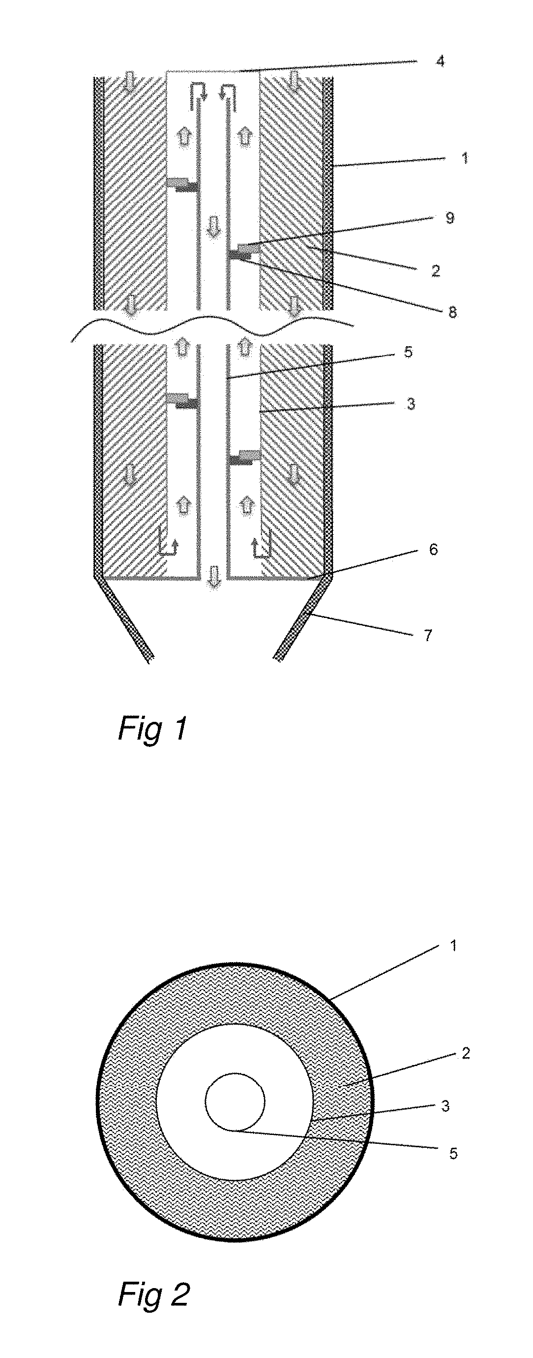
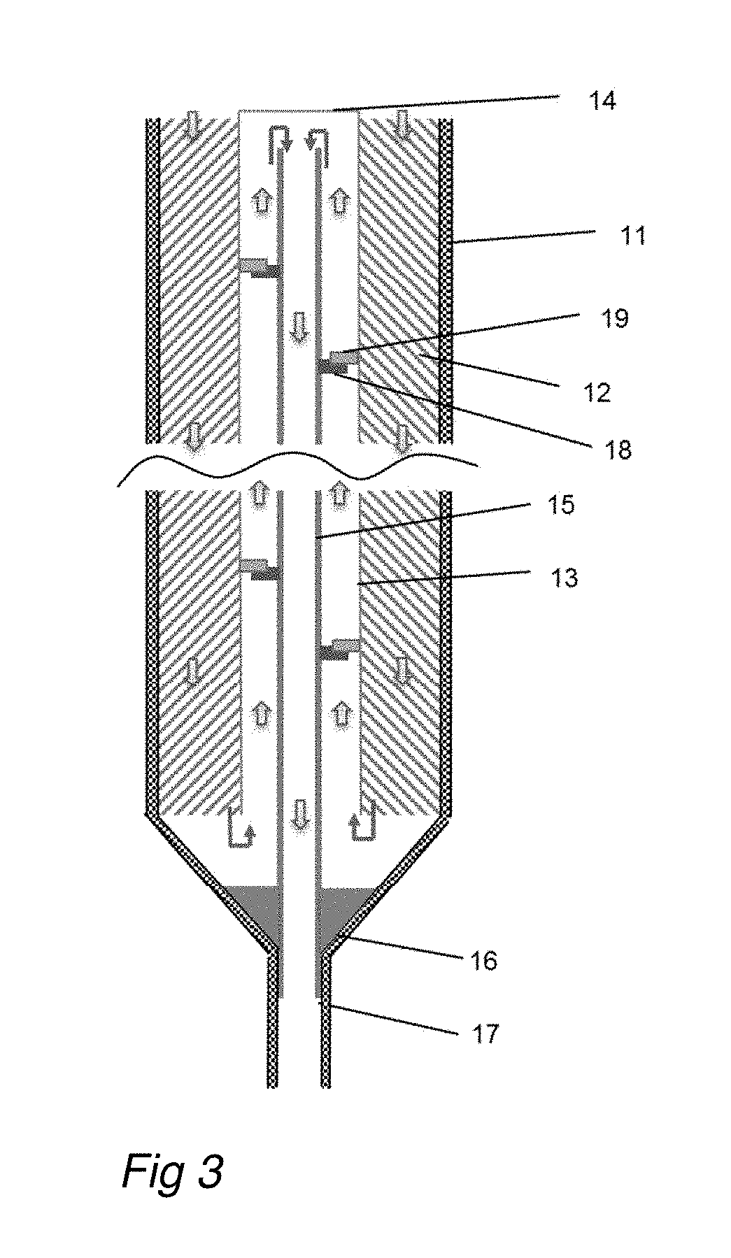
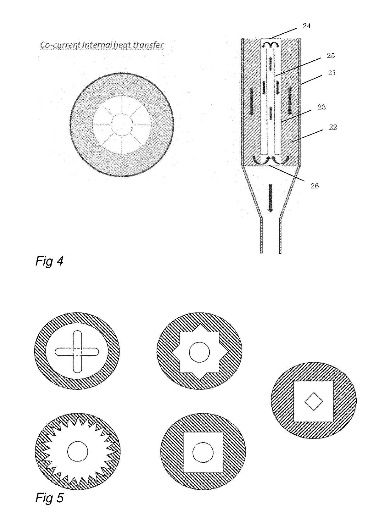
[0041]The term “annular channel” as used herein refers to the outer channel formed by positioning a first tube or tube-like body coaxially inside a second tube or tube-like body. The shape of the channel is thus determined by the shape of the outer wall of the first tube or tube-like body (which is the boundary in case of the first annular channel; and the inner tube in case of the second annular channel) and by the shape of the inner wall of the second tube or tube-like body (which is the catalyst tube in case of the first annular channel and the boundary in case of the second annular channel). In case of two round tubes, the cross-section of the annular channel will have the shape of a circular ring. However, as described below, the cross-section of the inner tube and of the boundary does not need to be circular. Accordingly, the annular channel can have various shapes. These shapes may also vary along the length of the catalyst tube.

[0042]For convenience sake, the term “process g...


PUM


Abstract

The inventions is directed to a new design for catalyst tubes, which makes it possible to apply the concept of regenerative reforming into steam reformers having catalyst tube inlets and outlets at opposite sides of the furnace chamber. The catalyst tube comprises an inlet for process gas to enter the catalyst tube and an outlet for process gas to exit the catalyst tube, which inlet and outlet are located at opposite ends of the catalyst tube. The catalyst tube further comprises a first annular channel comprising the catalyst, a second annular channel for process gas to flow countercurrently or co-currently to the process gas flowing through the first annular channel.

Description

CROSS-REFERENCE TO RELATED APPLICATIONS[0001]This Application is a U.S. National Stage application under 35 U.S.C. 371 of International Application No. PCT / EP2017 / 077345 filed on Oct. 25, 2017, which claims the benefit of priority to European Patent Application No. EP 16195490.4 filed on Oct. 25, 2016 in the European Patent Office. The entire contents of these applications are incorporated herein by reference in their entirety.BACKGROUND OF THE INVENTION1. Field of the Invention[0002]The invention is directed to a catalyst tube, a multitubular reactor, such as a steam reformer, comprising at least one of said catalyst tubes and a method for conducting a catalytic process such as steam reforming.2. Description of Related Art[0003]It is known to conduct catalytic processes in multitubular reactors. A well known example is the catalytic process of steam reforming.[0004]Steam reforming is a catalytic process, wherein a hydrocarbon feedstock (feed gas) is converted into a mixture of carb...

Claims


Application Information

Patent Timeline
IPC IPC(8): B01J8/02C01B3/38B01J8/06
CPCB01J8/0257C01B3/384B01J8/062B01J2208/00176B01J2208/00557B01J2208/00752B01J2208/0053B01J2208/065B01J2208/00194B01J2208/00539B01J2219/00024B01J2208/0092B01J2208/00221B01J2208/00761C01B3/38B01J2208/00504B01J2219/19B01J2219/1923B01J2219/1928B01J8/06
Inventor FARACE, ANTONIOWALSPURGER, STEPHANE
Owner TECH FRANCE SA
Learn More