Birefringent prism for wavelength separation

a wavelength separation and birefringent technology, applied in the field of optical elements for separating radiation, can solve the problems of reducing the sensitivity of the birefringent prism, causing damage to the thin-film optical coating, and limiting the effect of shorter-wavelength uv radiation, so as to achieve the effect of reducing the sensitivity of the birefringent coating and reducing the birefringent coating

Active Publication Date: 2019-11-12
COHERENT LASERSYST
View PDF19 Cites 4 Cited by
  • Summary
  • Abstract
  • Description
  • Claims
  • Application Information

AI Technical Summary

Problems solved by technology

A particular limitation of the laser arrangements described above is damage to thin-film optical coatings caused by the UV radiation.
This limitation becomes more problematic for shorter-wavelength UV radiation.
Further, even a not-yet-damaged coating will typically have losses due to manufacturing variances in layer-thickness or due to absorption by the materials of the coating.
Such losses reduce the efficiency of resonators having intra-cavity harmonic generation and ultimately the useful lifetime of these resonators.

Method used


Image

  • Birefringent prism for wavelength separation
  • Birefringent prism for wavelength separation
  • Birefringent prism for wavelength separation

Examples


Embodiment Construction

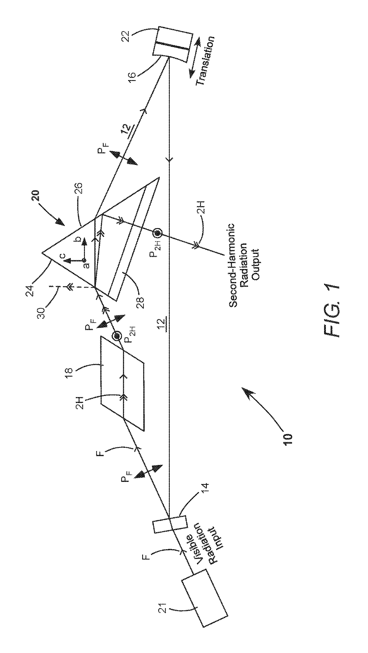
[0012]Turning now to the drawings, FIG. 1 schematically illustrates a preferred embodiment 10 of optical apparatus in accordance with the present invention. Apparatus 10 includes an optical resonator 12, which is configured as an enhancement resonator for harmonic conversion. Resonator 12 is a unidirectional ring-resonator formed by a plane mirror 14, a concave mirror 16, a Brewster-cut optically nonlinear crystal 18, and an uncoated birefringent out-coupling prism 20 in accordance with the present invention.

[0013]Visible wavelength radiation “F” is coupled into resonator 12 through mirror 14. The visible wavelength radiation is designated hereinafter as the “fundamental radiation”, for convenience of description. A source 21 of the fundamental radiation may generate the fundamental radiation by harmonic conversion of NIR radiation, as discussed above. By way of example, source 21 could be a diode-pumped OPS laser generating a beam of laser-radiation. The beam path of the fundamenta...


PUM

PropertyMeasurementUnit
wavelengthaaaaaaaaaa
Brewster angleaaaaaaaaaa

Abstract

An optical ring-resonator converts visible wavelength radiation to ultraviolet wavelength radiation by frequency-doubling the visible wavelength radiation in an optically nonlinear crystal. The resonator includes an uncoated birefringent out-coupling prism. The visible wavelength radiation passes through faces of the prism at a Brewster-angle. Ultraviolet wavelength radiation enters the prism, is totally internally reflected, directed out of the prism at a Brewster-angle, and exits the ring-resonator as output radiation.

Description

TECHNICAL FIELD OF THE INVENTION[0001]The present invention relates in general to optical elements for separating radiation having two components with different wavelengths. The invention relates in particular to optical elements for coupling ultraviolet wavelength radiation out of a laser resonator for visible wavelength radiation, in which the ultraviolet wavelength radiation is produced by second-harmonic conversion of the visible wavelength radiation.DISCUSSION OF BACKGROUND ART[0002]In devices for providing ultraviolet (UV) wavelength radiation it is usual to generate the ultraviolet wavelength radiation by harmonic conversion of visible wavelength radiation in an optically nonlinear crystal. Typically, the visible wavelength radiation is generated by second-harmonic conversion of near-infrared (NIR) wavelength radiation, which is generated in a solid-state laser, such as an optically-pumped semiconductor (OPS) laser.[0003]By way of example, in one common arrangement for genera...

Claims


Application Information

Patent Timeline
Patent Type & Authority Patents(United States)
IPC IPC(8): G02B5/30G02F1/37
CPCG02F1/37G02B5/3066G02B5/3083
Inventor SEELERT, WOLFVON ELM, RÜDIGER
Owner COHERENT LASERSYST
Why Eureka
Try Eureka