Structure of projection light string

a projection light and string structure technology, applied in the field of projection light string structure, can solve the problems of limiting the entertainment effect of this type of string, single images presented at a single angle may be not only tedious, but also non-variable, and achieve the effect of increasing the transfer distance of control signals

Active Publication Date: 2019-11-12
LIN CHIA HUA
View PDF5 Cites 4 Cited by
  • Summary
  • Abstract
  • Description
  • Claims
  • Application Information

AI Technical Summary

Benefits of technology

[0008]In a preferred embodiment, the control signal output buffer is used to boost the output power thereby increasing the transfer distance of the control signals.

Problems solved by technology

However, due to structural limitations, Christmas light strings are restricted by different color bodies, shapes, lighting methods of these light bulbs or else other possible factors, thus limiting the entertainment effects of this type of strings.
Moreover, most of currently available projection devices only enable projections of single images, whose internal configurations usually include various elements such as a set of illumination components, projection image films and lenses etc., and project the images of the placed projection films onto an assigned position by means of the illumination components through these lenses.
As such, integrally speaking, single images presented at a single angle may be not only tedious, but also non-variant.

Method used


Image

  • Structure of projection light string
  • Structure of projection light string
  • Structure of projection light string

Examples


Embodiment Construction

[0027]Other technical contents, aspects and effects in relation to the present invention can be clearly appreciated through the detailed descriptions concerning the preferred embodiments of the present invention in conjunction with the appended drawings.

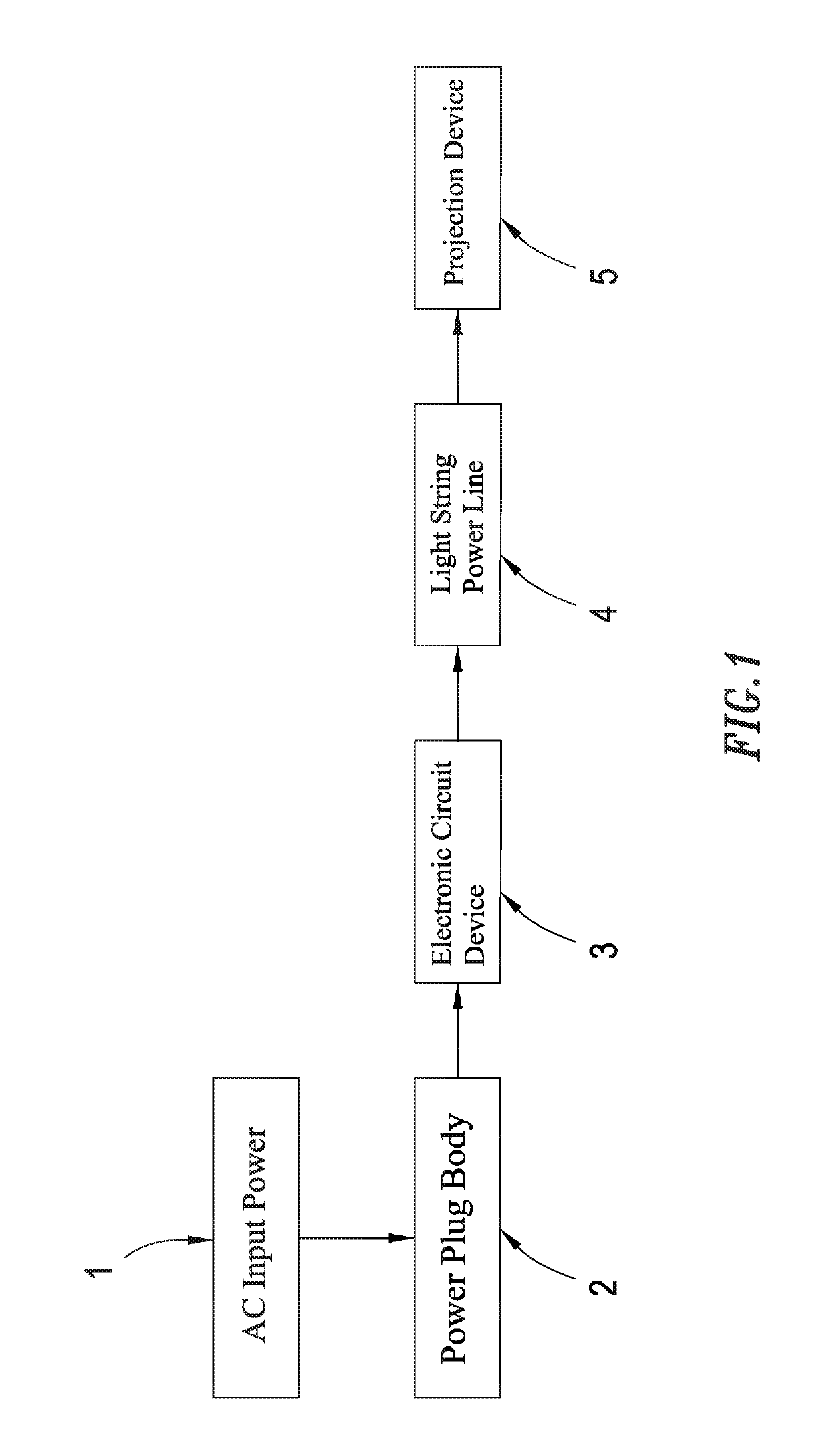
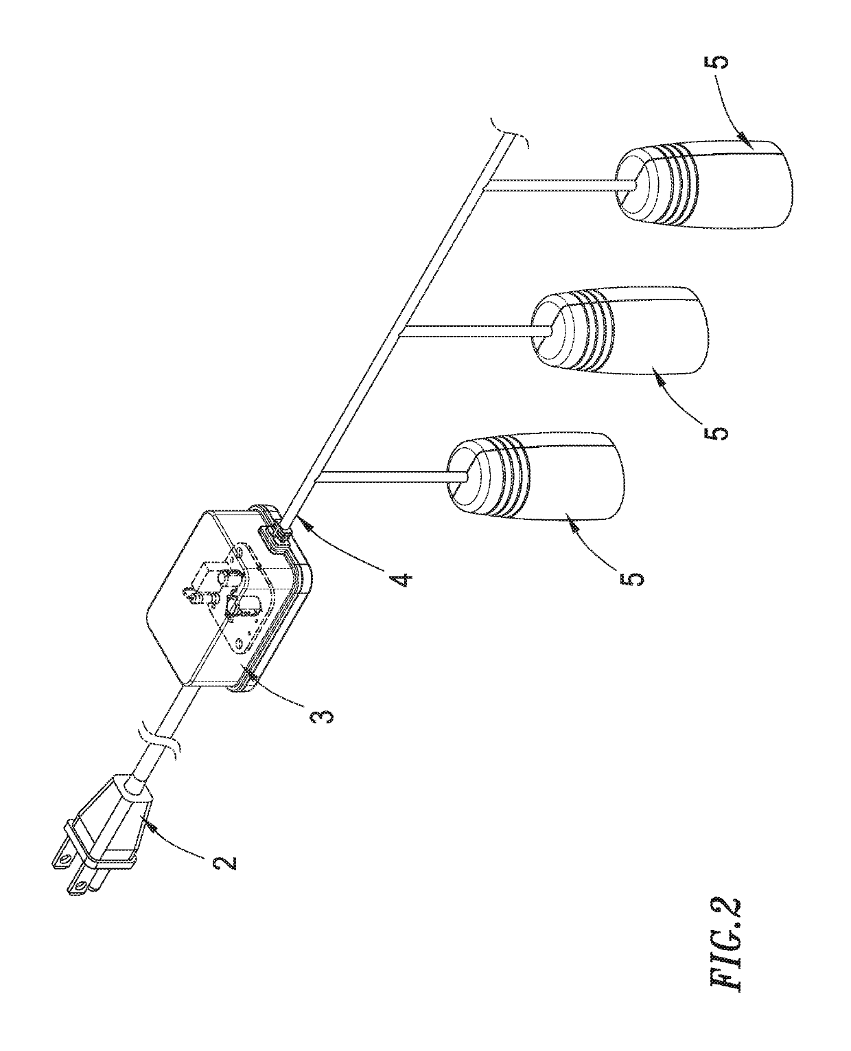
[0028]Refer now to FIGS. 1 and 2, wherein an overall architecture diagram as well as an implementation structure diagram for the structure of projection light string according to the present invention are respectively shown. As shown in the Figures, the disclosed structure of projection light string comprises a power plug body 2, an electronic circuit device 3, a lights string power line 4 and at least a projection device 5, in which the power plug body 2 is electrically connected to an alternative current (AC) input power 1 for inputting AC power, while the light string power line 4 internally includes multiple cables for feeding electric power and signals.

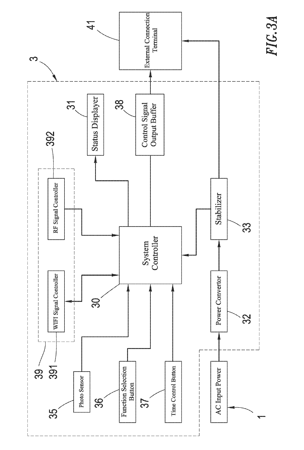
[0029]Herein the electronic circuit device 3 is electrically connected to the...


PUM


Abstract

A structure of projection light string is disclosed, comprising a power plug body, a light string power line, an electronic device and multiple projection devices installed in suspension over the light string power line, wherein the electronic circuit device is electrically connected to the power plug body and the light string power line, and further electrically connected to the projection devices by way of the power circuit within the light string power line; in addition, the inside of the projection device includes a projector capable of projecting images toward outside and a controller electrically connected to the projector, so that, after the electronic circuit device having transferred at least a projection time parameter and at least a projection mode parameter to the controller of each projection device, the controller can control the projection operations of the projector in accordance with the received projection time parameter and projection mode parameter.

Description

BACKGROUND OF THE INVENTION1. Field of the Invention[0001]The present invention generally relates to a structure of projection light string; in particular, it relates to a structure of projection light string capable of controlling different projection devices to project images by turns or simultaneously thereby allowing the observer to perceive the effect of continuous dynamic images because of visual persistence.2. Description of Related Art[0002]During Christmas days, it is customary to wrap a Christmas light string on a Christmas tree, house or other decorations in order to increase festival atmosphere with colorful Christmas lights. However, due to structural limitations, Christmas light strings are restricted by different color bodies, shapes, lighting methods of these light bulbs or else other possible factors, thus limiting the entertainment effects of this type of strings.[0003]Moreover, most of currently available projection devices only enable projections of single images...

Claims


Application Information

Patent Timeline
Patent Type & Authority Patents(United States)
IPC IPC(8): G03B21/20F21S4/10H05B37/02G03B21/14F21S4/00F21S8/00G02B27/09F21V23/02G03B29/00
CPCF21S4/00F21S8/035G03B29/00H05B37/0218G03B21/2013F21S4/10G03B21/2033F21V23/023G03B21/145G02B27/0955F21W2121/00H05B45/00H05B45/20H05B45/40H05B47/11Y02B20/40
Inventor LIN, CHIA-HUA
Owner LIN CHIA HUA
Why Eureka
Try Eureka