Wireless power transfer device and wireless power transfer method

a power transfer device and wireless technology, applied in the direction of electric vehicle charging technology, charging stations, transportation and packaging, etc., can solve the problems of short power transmission distance, difficult power efficient transfer, and dielectric loss, so as to increase the possible power transfer distance, achieve efficient power transfer, and reduce the effect of dielectric loss

Active Publication Date: 2013-04-04
MAXELL HLDG LTD
View PDF5 Cites 16 Cited by
  • Summary
  • Abstract
  • Description
  • Claims
  • Application Information

AI Technical Summary

Benefits of technology

[0017]According to the present invention, due to the configuration in which the power receiving coil is disposed in the power receiving space formed between the power transmission coil and the auxiliary coil, a distance dependency of the power transfer efficiency on the distance between the power transmitter and the power receiver can be made flat over a long range without the need to provide the power receiver with means for adjusting the resonant frequency, making it possible to increase the possible power transfer distance.
[0018]Therefore, it is possible to perform efficient power transfer even in the case where the power receiving coil is not appropriately disposed with respect to the power transmission coil, for example, where the surface suitable for power reception of the power receiver does not properly face the power transmitter. It is also possible to suppress the reduction in the power transfer efficiency, the reduction in the possible power transfer distance, and the like even when the size of the power receiving coil is small relative to that of the power transmission coil.

Problems solved by technology

Although this method is advantageous, for example, in that it can be realized with simple circuitry (a transformer), it also has the problem of a short power transmission distance.
Among them, in the electric field resonance type method, when placing the hand or the like in a transfer path, a dielectric loss is caused, because the human body, which is a dielectric, absorbs energy as heat.
In the condition of wirelessly transmitting and receiving power by the electromagnetic induction-type method or the magnetic field resonance-type method, if the power receiving coil unit is not appropriately disposed with respect to the power transmission coil unit, it is difficult to transfer power efficiently.
In such a case, when the portable power receiving coil unit is placed upside down, the shielding member is interposed between the power transmission coil unit and the power receiving coil unit, which results in a significant reduction in the transfer efficiency and makes power transfer difficult.
In the art disclosed in JP 2010-207017A, if the surface suitable for power reception of a power receiver does not properly face a power transmitter that supplies power, the user is merely warned by means of a sound or the like and eventually has to bring the surface back to the proper posture, making the operation troublesome.
Moreover, in the art disclosed in JP 2010-207017A, a magnetic sensor is provided on the power receiver side for the front / back discrimination, and therefore, it is difficult to provide such function other than the charging function in the power receiver if the power receiver is small (e.g., an in-the-ear hearing aid).
If the size of the power receiving coil unit is small relative to that of the power transmission coil unit, a reduction in the power transfer efficiency, a reduction in the possible power transfer distance, and the like may occur.
However, as described above, it is difficult to provide any additional function in the power receiver other than the charging function.

Method used


Image

  • Wireless power transfer device and wireless power transfer method
  • Wireless power transfer device and wireless power transfer method
  • Wireless power transfer device and wireless power transfer method

Examples


embodiment 1

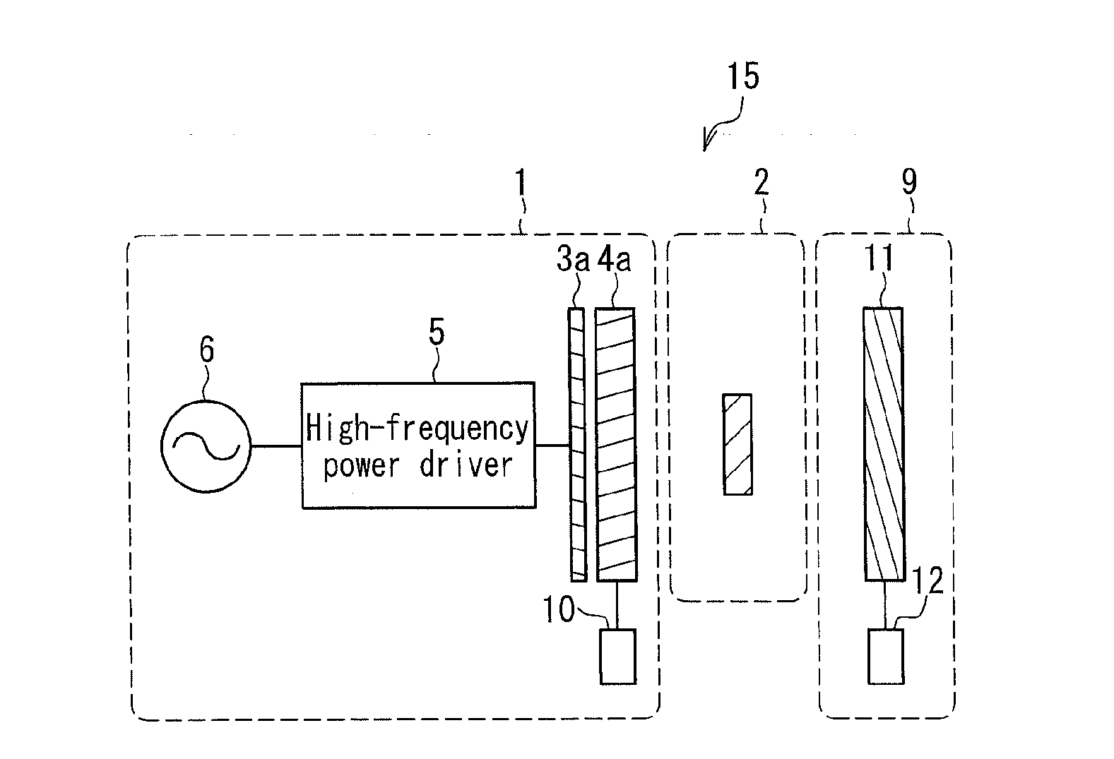
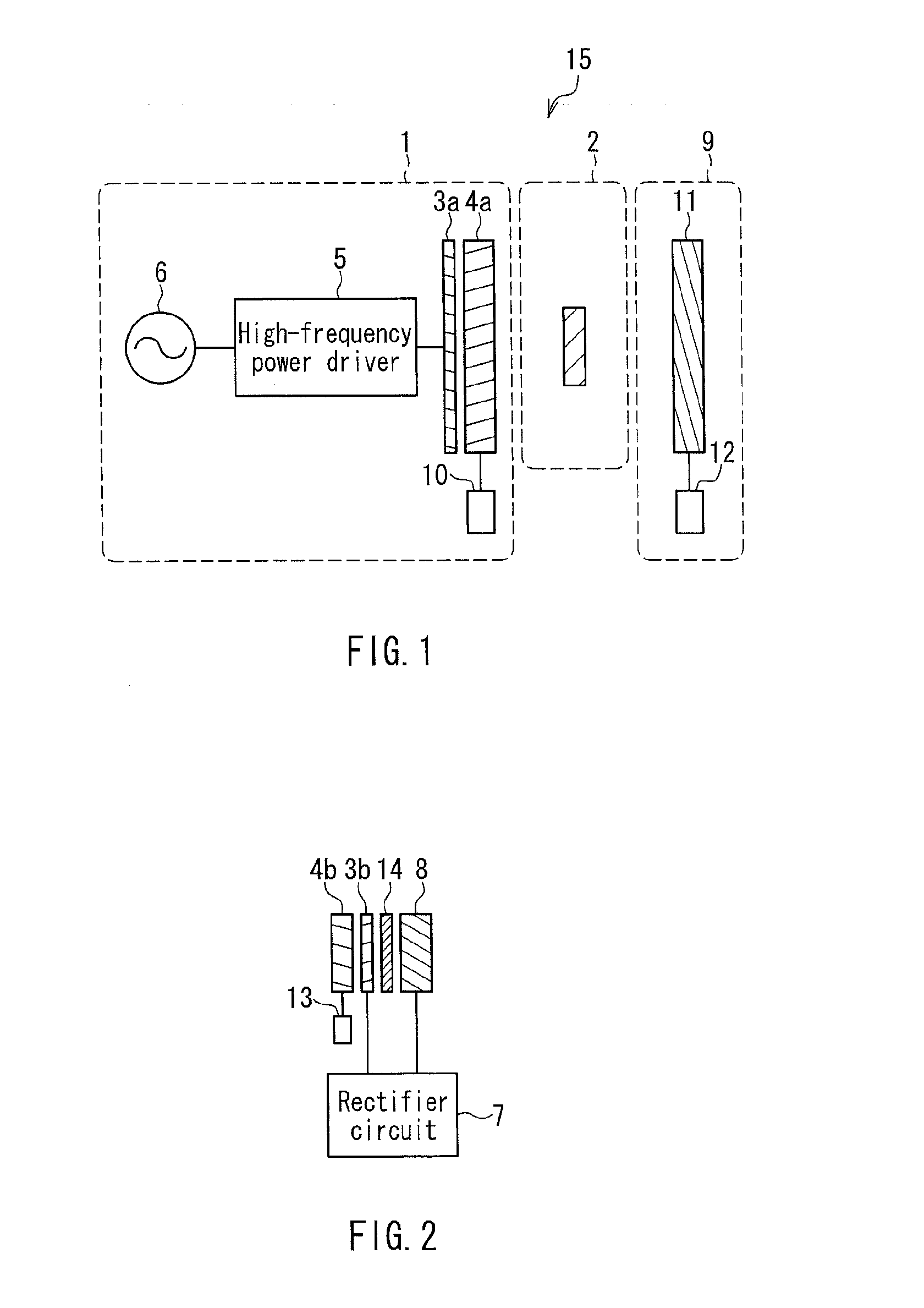
[0061]FIG. 1 is a cross-sectional view showing schematically the configuration of a wireless power transfer device of a magnetic field resonance type according to Embodiment 1. Note that the same elements as those of the conventional wireless power transfer device shown in FIG. 17 are denoted by the same reference numerals, and the description thereof will not be repeated.

[0062]This wireless power transfer device includes a power-transmission auxiliary device 9 in addition to the power transmitter 1 and the power receiver 2 of conventional technology, and is configured to perform wireless power transfer in a state in which the power receiver 2 is disposed in a space between the power transmitter 1 and the power-transmission auxiliary device 9. The power transmitter 1 converts power of an AC power supply (AC 100 V) into high-frequency power capable of being transmitted, and transfer the power, and the power receiver 2 receives the power. The power-transmission auxiliary device 9 has ...

embodiment 2

[0108]FIG. 15 is a cross-sectional view showing a wireless power transfer device according to Embodiment 2. This wireless power transfer device includes a vanity case-shaped (also called “music box-shaped”) casing 17 and a lid 18 that can be opened and closed, with the power transmitter 1 held in a lower interior portion of the casing 17 and the power-transmission auxiliary device 9 held by the lid 18. Provided above the power transmitter 1 is a support 19 for placing the power receiver 2, and the power receiver 2 (for example, a mobile phone or a hearing aid) can be installed onto the support 19. By closing the lid 18, the power receiver 2 is disposed between the power transmitter 1 and the power-transmission auxiliary device 9. Wireless power transfer is performed in this state.

[0109]The casing 17 is provided, for example, with a high-frequency power driver 5 that converts the power received from an AC power supply (AC 100 V) into power capable of being transmitted, and a control ...

embodiment 3

[0115]FIG. 16 is a cross-sectional view showing a wireless power transfer device according to Embodiment 3. The same elements as those of the configuration shown in FIG. 15 are denoted by the same reference numerals, and the description thereof will not be repeated.

[0116]This wireless power transfer device is an example in which a casing 24 is configured to be a vertical insertion type. More specifically, a housing portion for insertion of a mobile phone 26, which is an example of a device including the power receiver 2, is formed by a cavity portion 24a of a casing 24 and a recessed portion 25a of a lid 25, and the cavity portion 24a has a configuration that allows the mobile phone 26 to be a vertical insertion type. As in the case of Embodiment 2, the wireless power transfer device is provided with an interlock mechanism 27, and configured such that power transmission does not commence unless the lid 25 is completely closed.

[0117]With this configuration, the wireless power transfe...


PUM

PropertyMeasurementUnit
diameteraaaaaaaaaa
thicknessaaaaaaaaaa
thicknessaaaaaaaaaa

Abstract

A wireless power transfer device including: a power transmitter 1 including a power transmission resonator composed of a power transmission coil and a resonant capacitance; and a power receiver including a power receiving resonator composed of a power receiving coil and a resonant capacitance. The wireless power transfer device further includes a power-transmission auxiliary device including an auxiliary resonator composed of an auxiliary coil and a resonant capacitance. The power-transmission auxiliary device and the power transmitter are configured to be disposed so as to face each other, forming a power receiving space for disposing the power receiving coil between the power transmission coil and the auxiliary coil. An efficient power transfer can be performed without providing an adjusting circuit in the power receiver even when the power receiving coil is not appropriately disposed with respect to the power transmission coil.

Description

BACKGROUND OF THE INVENTION[0001]1. Field of the Invention[0002]The present invention relates to a wireless power transfer device and a wireless power transfer method of wireless power transfer via a power transmission coil provided in a power transmitter and a power receiving coil provided in a power receiver.[0003]2. Description of Related Art[0004]As methods of wireless power transfer, an electromagnetic induction type (several hundred kHz), electric or magnetic-field resonance type using transfer based on LC resonance through electric or magnetic field resonance, a microwave transmission-type using radio waves (several GHz), and a laser transmission-type using electromagnetic waves (light) in the visible radiation range are known. Among them, the electromagnetic induction type has already been used practically. Although this method is advantageous, for example, in that it can be realized with simple circuitry (a transformer), it also has the problem of a short power transmission...

Claims


Application Information

Patent Timeline
Patent Type & Authority Applications(United States)
IPC IPC(8): H02J17/00H01F38/14
CPCH04B5/0093H04B5/0037Y02T90/122Y02T10/7005Y02T90/14B60L11/182B60L53/126Y02T10/70Y02T10/7072Y02T90/12
Inventor MIYAUCHI, YASUSHIONUKI, SATORU
Owner MAXELL HLDG LTD
Why Eureka
Try Eureka