Heater

a heating tube and water tube technology, applied in the field of heaters, can solve the problems of high manufacturing cost, high heating wastage of heaters, and long heating time, and achieve the effects of improving heat transfer efficiency, good heat accumulation ability, and increasing heat generation of heating tubes

Inactive Publication Date: 2011-03-24
TSANN KUEN CHINA ENTERPRISE
View PDF4 Cites 1 Cited by
  • Summary
  • Abstract
  • Description
  • Claims
  • Application Information

AI Technical Summary

Benefits of technology

[0016]In the heater provided in the present invention, the heating tube and water tube are imbedded in the casting, and there are fully-filled fillings between the interstice between the heating tube and the water tube. Thus the casting has good heat accumulation ability, which makes the heat generated by the heating tube more concentrated resulting in higher heat transfer efficiency. This allows the provision of real-time hot water or rapid and continuous steam with high efficiency, and prevents excessive heat consumption, and achieving the object of energy-saving. In addition, because the heating tube is U-shaped, the overall heater structure is simple and easy to manufacture at lower cost. Further, because the water tube of the heater provided in the present invention is S-shaped, awhile the heating tube is U-shaped, the simple-structured heating tube thus works with the S-shape water tube to prolong the transfer distance of the water tube in a small space, and to that ensure the water has sufficient heating-absorption time.

Problems solved by technology

Because of the interstice which affects the heating-conduction efficiency among the heating tube, the water tube and the groove, these heaters have high heating wastage and requires long heating time.
The heating tube and the water tube are twisted to a cross spiral; however the structure of the heating tube and the water tube is highly complex, and has high manufacturing cost.

Method used


Image

  • Heater
  • Heater
  • Heater

Examples


Embodiment Construction

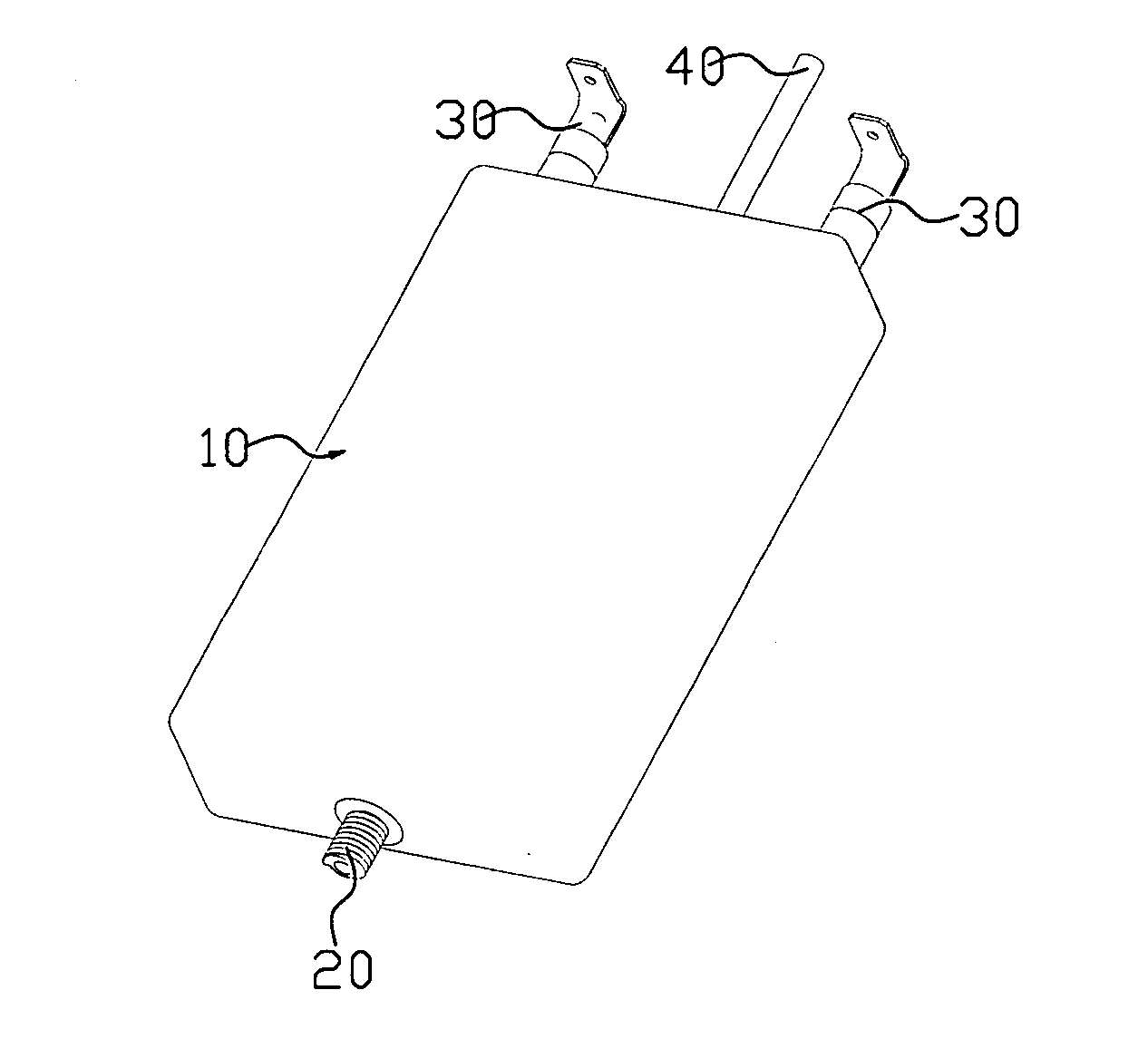
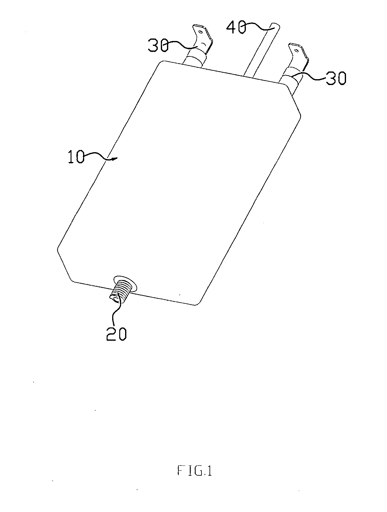
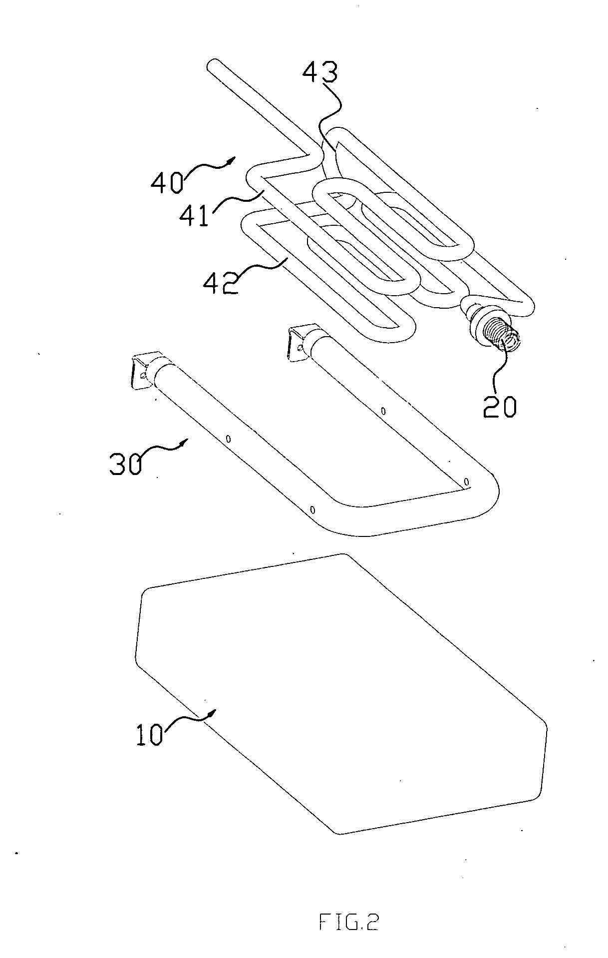
[0024]FIG. 1, FIG. 2 and FIG. 3, are the perspective view, exploded view and sectional view, respectively, of the heater in one preferred embodiment of the present invention respectively. The heater comprises a casting 10 and a pump body 20, wherein the casting 10 has a heating tube 30 embedded inside and a water tube 40 twisted around the outside of the heating tube 30. The Heater of the present invention can be used in coffee makers, but without limitation, it can also be used in other facilities such as water dispenser.

[0025]The heating tube 30 is U-shaped and has two electric connection terminals for connecting to power, the two terminals extending out of the same side of the casting 10.

[0026]The water tube 40 has an inlet and an outlet extending out of the casting 10, wherein the inlet and outlet extend out the opposite sides of the casting 10 respectively. The pump body 20 is connected to the water inlet for providing continual water. The water tube 40 includes a serially-conn...


PUM


Abstract

A heater comprises a cast casing, a heating tube and a water tube coiled on the heating tube imbedded in the cast, wherein the heating tube is U-shaped and has two electric terminals for connecting to the power, and the water tube has an inlet and an outlet extending out of the casting. Because the heating tube and water tube are imbedded in the casting, and there are fillings that fully fill the interstice between the heating tube and the water tube, the casting has good heat accumulation ability, which allows the heat generated by the heating tube to be highly concentrated to achieve high heat transfer efficiency.

Description

FIELD OF THE INVENTION[0001]The present invention relates to a heater.BACKGROUND OF THE INVENTION[0002]Traditional heaters comprise a base board, a heating tube and a water tube, the base board has a groove for containing the heating tube and the water tube. When power is provided to the heating tube, heat will be transferred from the heating tube to the water tube by way of thermal conduction to heat up the water in the water tube. Because of the interstice which affects the heating-conduction efficiency among the heating tube, the water tube and the groove, these heaters have high heating wastage and requires long heating time.[0003]In order to remedy the above mentioned deficiency, a solution has been provided in Chinese patent No. 200520065015.2, entitled “An electric heater for coffee maker,” and published on Oct. 11, 2006. The electric heater disclosed herein includes a casting used as a base, a heating tube and a water tube, the heating tube and the water tube being embedded ...

Claims


Application Information

Patent Timeline
Patent Type & Authority Applications(United States)
IPC IPC(8): H05B3/40B67D7/82
CPCA47J27/21008A47J31/542H05B2203/021H05B3/48F24H1/142
Inventor LIN, KUOHSUNHONG, CHUNJIE
Owner TSANN KUEN CHINA ENTERPRISE
Why Eureka
Try Eureka