Image measuring device and program

a technology of image measurement and program, which is applied in the field of image measurement device and program, can solve the problems of unlikely non-uniform brightness and distortion of the lens, and achieve the effects of high accuracy, increased cost, and high speed

Active Publication Date: 2019-11-12
MITUTOYO CORP
View PDF13 Cites 0 Cited by
  • Summary
  • Abstract
  • Description
  • Claims
  • Application Information

AI Technical Summary

Benefits of technology

[0012]The present invention provides an image measuring device and a program capable of image stitching with high accuracy and high speed without an increase in cost.
[0014]By setting the image capture region of an area sensor as a line sensor in this way, a frame rate of image capture can be increased and allows capturing a large number of images. In addition, the image capture region is a narrow line and therefore, non-uniform brightness and distortion of a lens are unlikely to occur in the short direction of the captured partial linear image. Therefore, by capturing a plurality of the partial linear images without sequential gaps while displacing the image capturer relative to the measured object, the image capturer having the image capture region set as the line sensor, and pasting together the plurality of partial linear images, an image can be obtained without a border or offset in a direction along which the image capturer is displaced. Accordingly, when the plurality of partial images are pasted together in a conventional image capture method, a lattice pattern has been generated by the border and offset caused by the non-uniform brightness and the lens distortion of the respective partial images. Such an image, which would have a lattice pattern using the conventional method, can be limited to generating stripe-like borders and offset, and therefore, image stitching can be performed with a high degree of accuracy as compared to the conventional image capture method. In addition, image capture is performed while displacing the image capturer, and therefore image capturing time can be shortened and pasting accuracy can be prevented from decreasing due to the device behavior being unstable. Furthermore, a light source is sufficient that is capable of emitting enough light at a portion of the measured object where the linear region is captured by the image capturer and the cost of the device can be reduced because a device capable of illuminating a broad area is not required.
[0015](2) When the image stitching is not necessary, setting the image capture region of the image capturer may be configured to be switchable between a linear portion and a total region since there are cases where capturing images without narrowing down the image capture region may be more efficient.
[0017]Data of the partial image and the image capture position coordinates of the partial image data are individually obtained before forming the total image; however, the image data has the index indicating the image capture order and the position coordinates also have the count value indicating the image capture order. Therefore, both can be associated with each other, even when obtained asynchronously, using the respectively assigned image capture order. Therefore, an error factor from an uncertain delay in at least one of the image capture orders can be eliminated.
[0018](4) A relative displacement speed between the measured object and the image capturer may be changeable using the controller. Measurement can be performed quickly by increasing the displacement speed; however, time of exposure toward the image capture position is decreased and so is the measurement accuracy. The displacement speed corresponding to the required accuracy can be selected by making the displacement speed changeable.

Problems solved by technology

In addition, the image capture region is a narrow line and therefore, non-uniform brightness and distortion of a lens are unlikely to occur in the short direction of the captured partial linear image.

Method used


Image

  • Image measuring device and program
  • Image measuring device and program
  • Image measuring device and program

Examples


Embodiment Construction

[0028]The particulars shown herein are by way of example and for purposes of illustrative discussion of the embodiments of the present invention only and are presented in the cause of providing what is believed to be the most useful and readily understood description of the principles and conceptual aspects of the present invention. In this regard, no attempt is made to show structural details of the present invention in more detail than is necessary for the fundamental understanding of the present invention, the description taken with the drawings making apparent to those skilled in the art how the forms of the present invention may be embodied in practice.

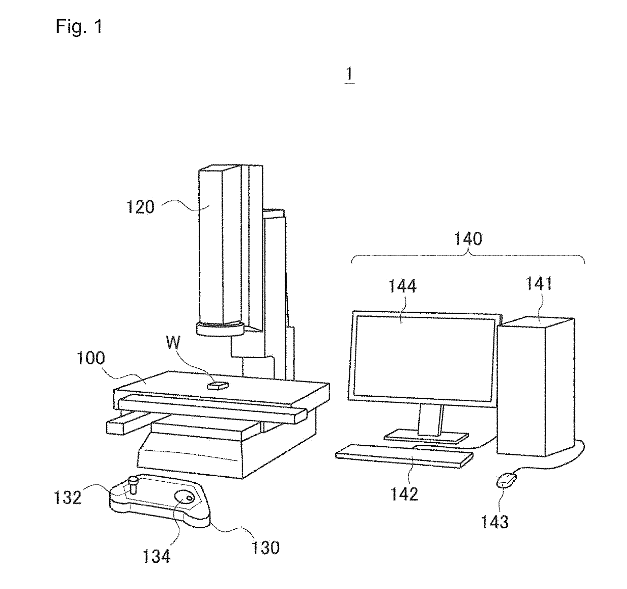
[0029]Hereafter, an embodiment of the present invention is described with reference to the drawings. FIG. 1 is a perspective view illustrating a configuration of an image measuring device 1. The image measuring device 1 includes a stage 100, a position acquirer 110, an image capture unit 120, a remote box 130, and a computer syst...


PUM


Abstract

An image measuring device includes an image capturer capturing an image of a work piece, a displacer relatively displacing the work piece and the image capturer, a position acquirer obtaining a position where the image is captured by the image capturer, a controller controlling the image capturer to capture partial images of the work piece while displacing the image capturer relative to the work piece at a fixed speed using the displacer, a total image former forming a total image of the work piece by pasting together a plurality of partial images captured by the image capturer based on position data obtained by the position acquirer, and a light source integrally displacing with the image capturer relative to the work piece and emitting light at a portion of the work piece captured by the image capturer.

Description

CROSS-REFERENCE TO RELATED APPLICATIONS[0001]The present application claims priority under 35 U.S.C. § 119 of Japanese Application No. 2016-021306, filed on Feb. 5, 2016, the disclosure of which is expressly incorporated by reference herein in its entirety.BACKGROUND OF THE INVENTION[0002]1. Field of the Invention[0003]The present invention relates to an image measuring device and a program measuring a shape of a measurable object without contact, based on an image obtained by capturing the image of the measured object.[0004]2. Description of Related Art[0005]The image measuring device is a device capturing an image of a measured object (hereafter referred to as a “work piece”); analyzing the image; extracting a shape such as a straight line, circle, polygon and the like; and obtaining measurement results such as distance, inclination, diameter, width, and the like of the extracted shape.[0006]The work piece comes in various sizes and when measuring a work piece which fails to fit i...

Claims


Application Information

Patent Timeline
Patent Type & Authority Patents(United States)
IPC IPC(8): G06T7/62G06T7/70H04N5/225H04N5/262
CPCH04N5/2256H04N5/225H04N5/2624G06T7/70G06T7/62G06T2207/20221G06T2207/30164G01B11/00G01B11/24H04N23/56H04N23/00
Inventor YOSHIDA, HIROYUKI
Owner MITUTOYO CORP
Why Eureka
Try Eureka