Device for assembling cams on a camshaft pipe

Active Publication Date: 2019-11-19
MAHLE INT GMBH
View PDF13 Cites 0 Cited by
  • Summary
  • Abstract
  • Description
  • Claims
  • Application Information

AI Technical Summary

Benefits of technology

[0007]With a further advantageous embodiment of the solution according to the invention, a first gripper comprises two jaws that are moveable against one another, which clamp the cam to be gripped between them. These two jaws are moved apart for receiving and for fixing the cam subject to clamping the same in-between, are clamped against one another. Usually, contact bodies are arranged on the two jaws which bring about a comparatively small heat-transferring contact area with the gripped cam, so that the cam that is heated for the thermal joining is not subjected to an undesirably high heat outflow via the first gripper.
[0008]Practically, a second gripper of the device comprises a U-shaped seat and a likewise U-shaped holder that can be axially and radially moved relative to the former. Here, two con

Problems solved by technology

With previous grippers, which usually comprised two jaws that can be moved relative to one another, reliable gripping of the cam is only possible in particular when the same can be gripped on its longitudinal sides.

Method used


Image

  • Device for assembling cams on a camshaft pipe
  • Device for assembling cams on a camshaft pipe
  • Device for assembling cams on a camshaft pipe

Examples


Embodiment Construction

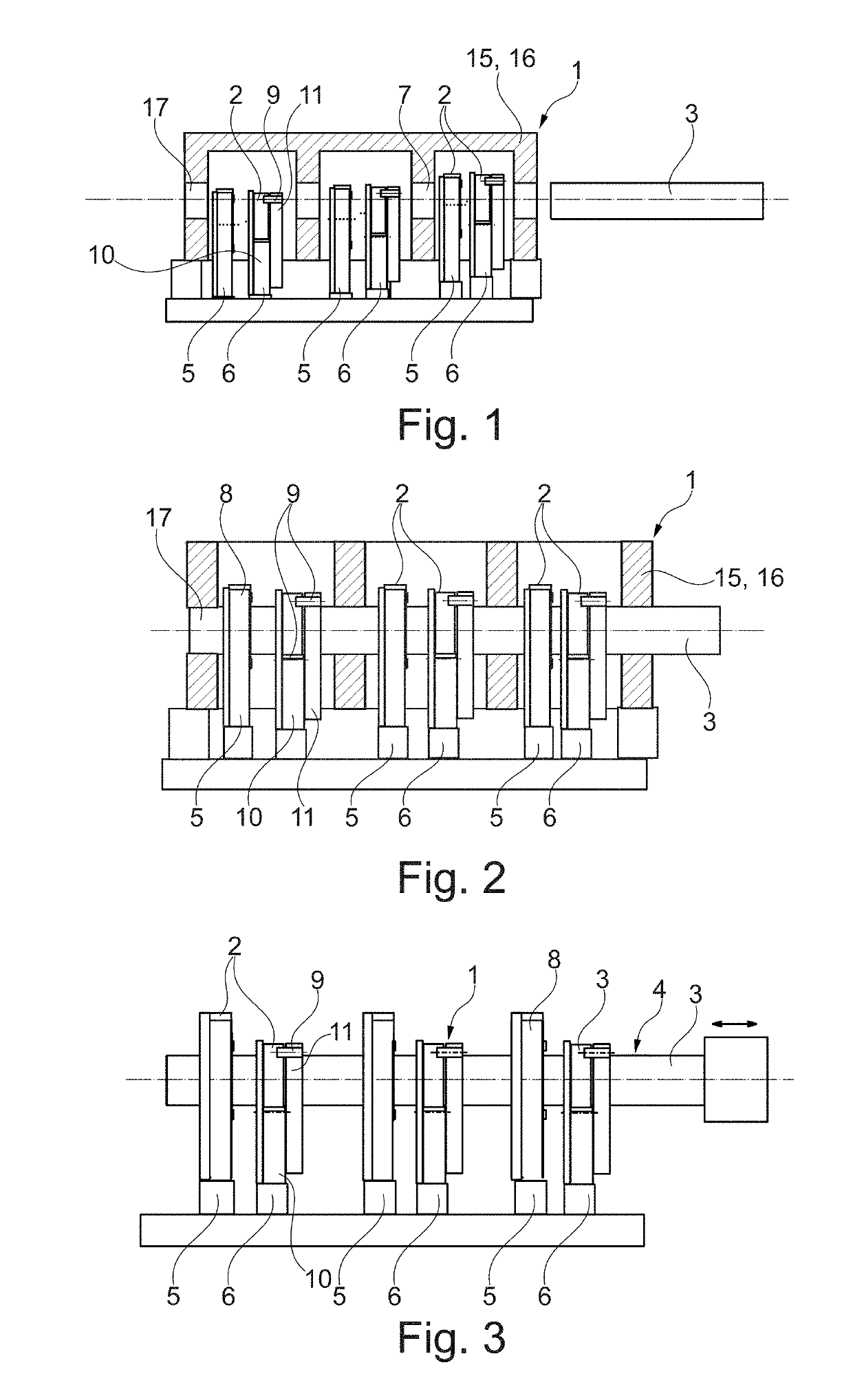
[0022]According to FIGS. 1 to 3, a device 1 according to the invention for assembling cams 2 on a camshaft pipe 3 of a camshaft 4 comprises at least one first gripper 5 and a second gripper 6 for gripping and holding the cams 2 during the assembly process. The devices 1 according to FIGS. 1 to 3 in this case each comprise three first grippers 5 and three second grippers 6. All grippers 5, 6 in this case can be fitted with cams 2 from the same direction, according to FIGS. 1 to 3 from above and moved in the same direction into alignment with the camshaft pipe 3. In the shown case, the individual grippers 5, 6 can be vertically adjusted in such a manner that the cams 2 which are fixed in the grippers 5, 6 are orientated with their cam bore 7 aligned with the camshaft pipe 3. According to the invention, the second gripper 6 is now able to hold a cam 2 pivoted by 90° with respect to the cam 2 held in the first gripper 5. Because of this, not only a particularly installation space-optimi...


PUM

PropertyMeasurementUnit
Angleaaaaaaaaaa
Shapeaaaaaaaaaa

Abstract

A device for assembling cams on a camshaft pipe of a camshaft may include a first gripper and a second gripper each configured for gripping and holding a respective cam. The first gripper and the second gripper may receive the respective cam in a common direction and may be movable in a common direction into alignment with respect to the camshaft pipe. The second gripper may be configured to grip and hold the respective cam that is pivoted by 90° with respect to an orientation of the respective cam in the first gripper.

Description

CROSS-REFERENCE TO RELATED APPLICATIONS[0001]This application claims priority to German Patent Application No. 10 2013 215 711.8, filed Aug. 8, 2013, and International Patent Application No. PCT / EP2014 / 063673, filed Jun. 27, 2014, both of which are hereby incorporated by reference in their entirety.TECHNICAL FIELD[0002]The present invention relates to a pipe for assembling cams on a camshaft pipe of a camshaft with at least one first gripper and a second gripper for gripping and holding the cams during the assembly process. The invention, furthermore, relates to a method for thermally joining cams on a camshaft pipe using such a device and to a second gripper for such a device.BACKGROUND[0003]Generic devices are thoroughly known and have been industrially employed for a long time for the automated production of camshafts. Disadvantageous with the known devices however is that because of the grippers, all cams have to be gripped in the same manner and by pivoting the camshaft pipe ha...

Claims


Application Information

Patent Timeline
IPC IPC(8): F01L1/047B23P11/02F16H53/02
CPCF16H53/025B23P11/025F01L1/047B23P2700/02F01L2103/01F01L2001/0471F01L2303/01
Inventor DAUTEL, FRANKFLENDER, THOMASMENONNA, ANTONIOSTEICHELE, STEFAN
Owner MAHLE INT GMBH
Why Eureka
Try Eureka