
Waterproof connector and device with connector

Active Publication Date: 2020-07-16
YAZAKI CORP
View PDF0 Cites 1 Cited by
  • Summary
  • Abstract
  • Description
  • Claims
  • Application Information

AI Technical Summary

Benefits of technology

The present invention provides a waterproof connector and device that use a seal member to prevent water from entering the connector. The seal member is attached to the connector main body and the tapered opening, ensuring a larger contact area compared to an O-ring. This allows for easy design and manufacture of the seal member, and prevents displacement during installation. The invention simplifies the process of designing and aligning the through-hole with the tapered opening, and ensures a secure and effective waterproof connection.

Problems solved by technology

In such a configuration, there is a concern that water may enter between the connector and the inner periphery of the through-hole, and some waterproofing measures are often taken.
On the other hand, from the viewpoint of waterproofing, care must be taken because the gap between the outer peripheral surface of the connector and the inner peripheral surface of the tapered opening tends to be large.

Method used


Image

  • Waterproof connector and device with connector
  • Waterproof connector and device with connector
  • Waterproof connector and device with connector

Examples


first embodiment

[0031]Hereinafter, embodiments of the present invention will be described. First, a first embodiment will be described.

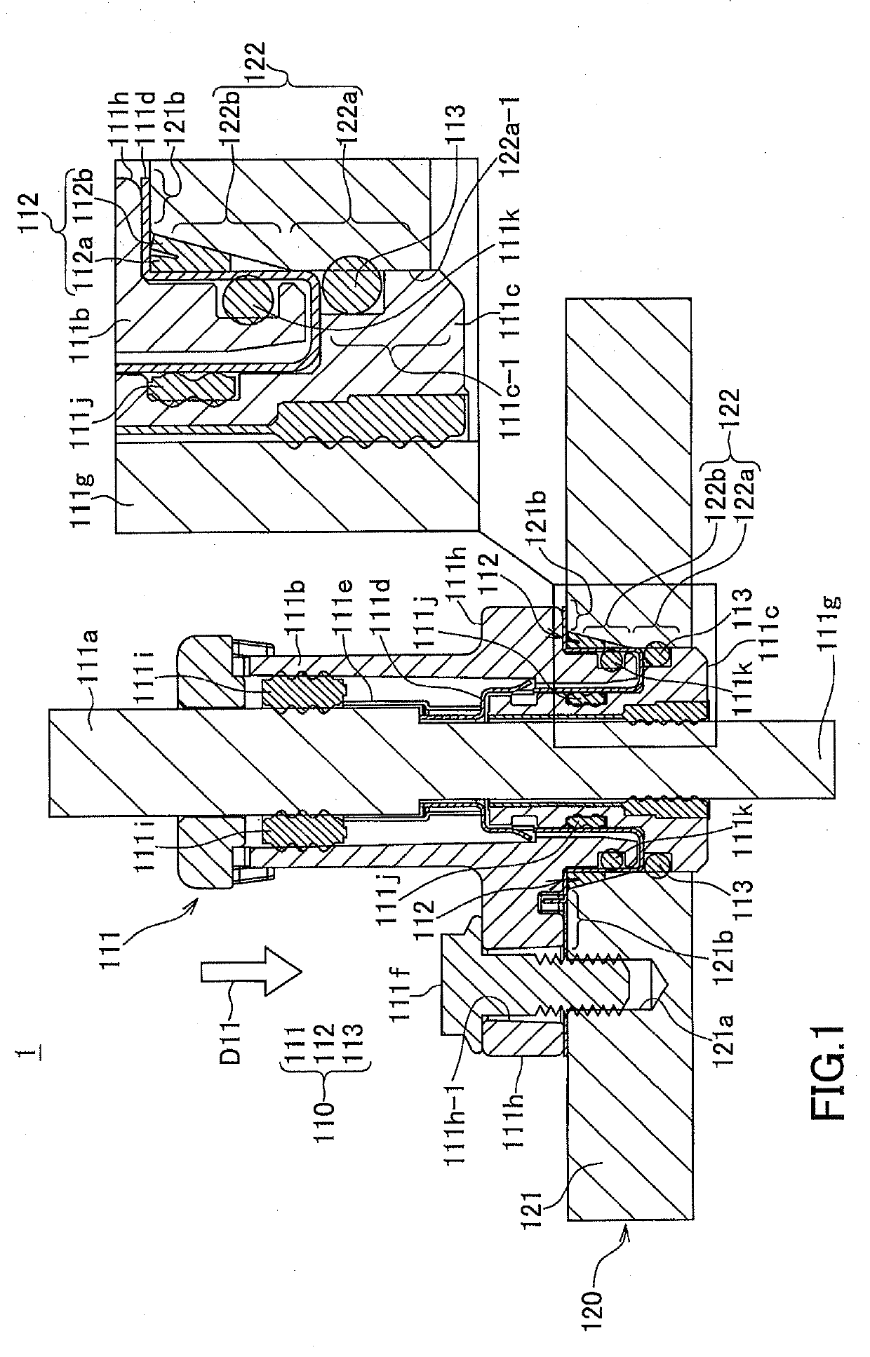
[0032]FIG. 1 is a schematic view showing a device with a connector according to the first embodiment of the present invention. In FIG. 1, the device with the connector 1 is shown in a schematic cross-sectional view of a waterproof connector 110 and an outer wall 121 in the vicinity of an attachment location of the waterproof connector 110 in a device 120.

[0033]In the device 120, a through-hole 122 as an attachment location of the waterproof connector 110 is provided on the outer wall 121. The through-hole 122 is provided with a tapered opening 122b as an opening at the end of the cylindrical-hole-shaped hole main body 122a outside of the device. The tapered opening 122b is a mortar-shaped opening that has a larger diameter than the inside of the device and is reduced in diameter toward the inside of the device.

[0034]The waterproof connector 110 is partly inserted in...

second embodiment

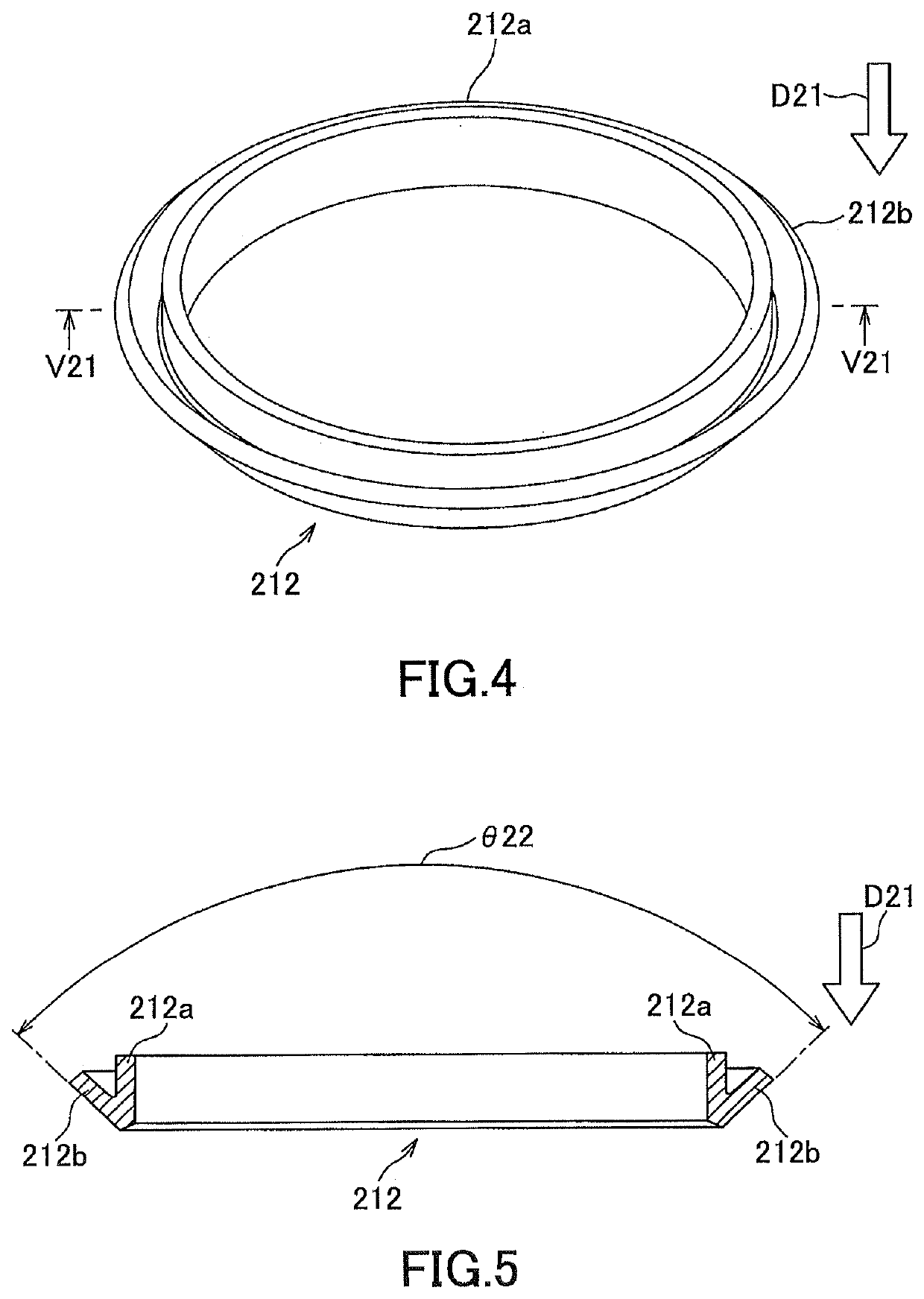
[0060]FIG. 4 is an external perspective view of a seal member according to the present invention, and FIG. 5 is a cross-sectional view showing a radial cross section of the seal member taken along the line V21-V21 in FIG. 4.

[0061]As shown in FIGS. 5 and 4, the seal member 212 of the present embodiment is different from the first embodiment in that the inner tube portion 212a integrated with the outer tube portion 212b has a straight cylindrical shape that has the same diameter from one end to the other end in the insertion direction D21. Further, the taper angle θ22 of the outer tube portion 212b is larger than the taper angle θ12 of the outer tube portion 112b in the first embodiment described above. The inner tube portion 212a and the outer tube portion 212b are integrated with each other on the front side in the insertion direction D21. As shown in FIG. 5, in the radial cross section of the seal member 212, the inner tube portion 112a and the outer tube portion 112b form a substa...

third embodiment

[0065]FIG. 6 is an external perspective view of a seal member according to the present invention, and FIG. 7 is a cross-sectional view showing a radial cross section of the sealing member taken along line V31-V31 in FIG. 6.

[0066]Like the second embodiment described above, the inner tube portion 312a of the seal member 312 has a straight cylindrical shape that has the same diameter from one end to the other end in the insertion direction D31 into the tapered opening 122b. Further, like the second embodiment, the taper angle θ32 of the outer tube portion 312b is larger than the taper angle θ12 of the outer tube portion 112b in the first embodiment described above.

[0067]Here, in the present embodiment, the outer tube portion 312b is formed so that the front side in the insertion direction D31 is integrated with the inner tube portion 312a at a midway position in the insertion direction D31 of the inner tube portion 312a. For this reason, as shown in FIG. 7, the seal member 312 before b...


PUM


Abstract

A seal member for waterproofing in the waterproof connector includes: a cylindrical inner tube portion that is face-to-face attached to an outer peripheral surface of a connector main body that is attached to a through-hole provided with a tapered opening; and an outer tube portion surrounding the inner tube portion in a circumferential direction at a rear side of an insertion direction into the tapered opening and opening in a larger diameter than the inner tube portion, and integrated with the inner tube portion at a front side in the insertion direction, and when the seal member is received between the outer peripheral surface of the connector main body and an inner peripheral surface of the tapered opening, face-to-face attached to the inner peripheral surface of the tapered opening while being pressed toward the inner tube portion.

Description

TECHNICAL FIELD[0001]The present invention relates to a waterproof connector that is attached to a through-hole provided in an outer wall of a device and is waterproofed, and a device with a connector.BACKGROUND ART[0002]Conventionally, a device direct attachment type connector that is attached to a through-hole provided in an outer wall of a device is known. Such a connector is attached by inserting a part thereof into the through-hole. In such a configuration, there is a concern that water may enter between the connector and the inner periphery of the through-hole, and some waterproofing measures are often taken.[0003]Here, some through-holes for attaching a connector in a device have a tapered opening in which an opening on the outside of the device is opened to a diameter larger than that on the inside of the device and is reduced toward the inside of the device. Such a tapered opening serves as an insertion guide when the connector is inserted into the through-hole, leading to ...

Claims


Application Information

Patent Timeline
IPC IPC(8): F16J15/3232
CPCF16J15/3232H02G3/22H01R13/5227H01R13/5205H01R13/502F16J15/3236H01R9/0524H02G15/013H01R13/5202
Inventor CHIKAMATSU, YASUKAZUMASUDA, SATOKI
Owner YAZAKI CORP
Features
  • Generate Ideas
  • Intellectual Property
  • Life Sciences
  • Materials
  • Tech Scout
  • Unparalleled Data Quality
  • Higher Quality Content
  • 60% Fewer Hallucinations
Learn More