
Electrical switching apparatus and clinch joint assembly therefor

Active Publication Date: 2017-05-18
EATON INTELLIGENT POWER LIMITED
View PDF1 Cites 0 Cited by
  • Summary
  • Abstract
  • Description
  • Claims
  • Application Information

AI Technical Summary

Benefits of technology

The disclosed and claimed invention is a movable contact assembly for an electrical switching apparatus. The assembly includes a number of shunts and a carriage assembly with two sidewalls and a contact arm assembly. The contact arm assembly includes a plurality of contact arms, isolation members, movable contacts, and an axle. Each contact arm is rotatably coupled to the axle with the axle extending through the contact arm opening. Each isolation member is disposed adjacent at least one contact arm. Each isolation member is coupled to, and in electrical communication with, the adjacent contact arm. The shunts are coupled to, and in electrical communication with, the isolation members. The technical effect of this invention is that the area of each contact arm that frictionally engages another element is limited to the isolation member, which may result in easier control of the frictional force generated by the smaller contact area. Additionally, no shunt operatively engages a contact arm, thereby improving the stability and reliability of the movable contact assembly.

Problems solved by technology

One of the disadvantages associated with known wire rope or braided-type shunts is that they do not fit well within the limited spacing which is available between the adjacent contact arms of the movable contact assembly.
Specifically, the body of such shunts tends to expand outward and occupy more than the width of the finger, thus interfering with adjacent structures.
The wire ropes also tend to bunch together during short circuit events, thus inhibiting the flexibility of the assembly.
This is problematic in view of the compound motion which the fingers experience as a result of the well-known “heel-toe” and / or “blow-on” arcing schemes which are commonly employed by low-voltage circuit breakers.
This motion causes the shunt to wear and creates uncontrollable forces that affect the carrier and contact arms.
Among them is the fact that they are typically V-shaped, thus having a single relatively sharp bend which undesirably creates an area of stress concentration.
This V shape also consumes a substantial amount of valuable space within the molded housing of the circuit breaker.
Thus, there is a problem with the size and configuration, including the use shape, of shunts.
That is, shunt loads are not isolated from the movable contact assembly contact arms, and, longer shunts are subject to extreme compound deflection.
This is a disadvantage as the variable forces enhance, or detract from, the opening forces created by the operating mechanism.
That is, having an operating mechanism that has variable opening characteristics is a disadvantage.
This is only possible with a two-arm configuration because the torqued applied by a yoke to a medial contact arm, i.e., a contact arm between two other contact arms, cannot be controlled.
This is a disadvantage because the rating, i.e., withstand value, or, the size, of the circuit breaker is limited by the size of the movable contact assembly contact arms.
Thus, there is a problem with the size and configuration of clinch joint assemblies.
Further, the limited number of movable contact assembly contact arms allowed by present clinch joint assemblies is a problem.
That is, an air circuit breaker that utilizes a moving clinch joint assembly is subject to the problems of both clinch joint assemblies and shunts noted above.

Method used


Image

  • Electrical switching apparatus and clinch joint assembly therefor
  • Electrical switching apparatus and clinch joint assembly therefor
  • Electrical switching apparatus and clinch joint assembly therefor

Examples


Embodiment Construction

[0031]Directional phrases used herein, such as, for example, clockwise, counterclockwise, left, right, top, bottom, upwards, downwards and derivatives thereof, relate to the orientation of the elements shown in the drawings and are not limiting upon the claims unless expressly recited therein.

[0032]As used herein, the singular form of “a,”“an,” and “the” include plural references unless the context clearly dictates otherwise.

[0033]As used herein, the word “unitary” means a component is created as a single piece or unit. That is, a component that includes pieces that are created separately and then coupled together as a unit is not a “unitary” component or body. Further, as used herein, the portions or elements of a “unitary” body are “coupled” together.

[0034]As used herein, a “coupling assembly” includes two or more couplings or coupling components. The components of a coupling or coupling assembly are generally not part of the same element or other component. As such, the component...


PUM


Abstract

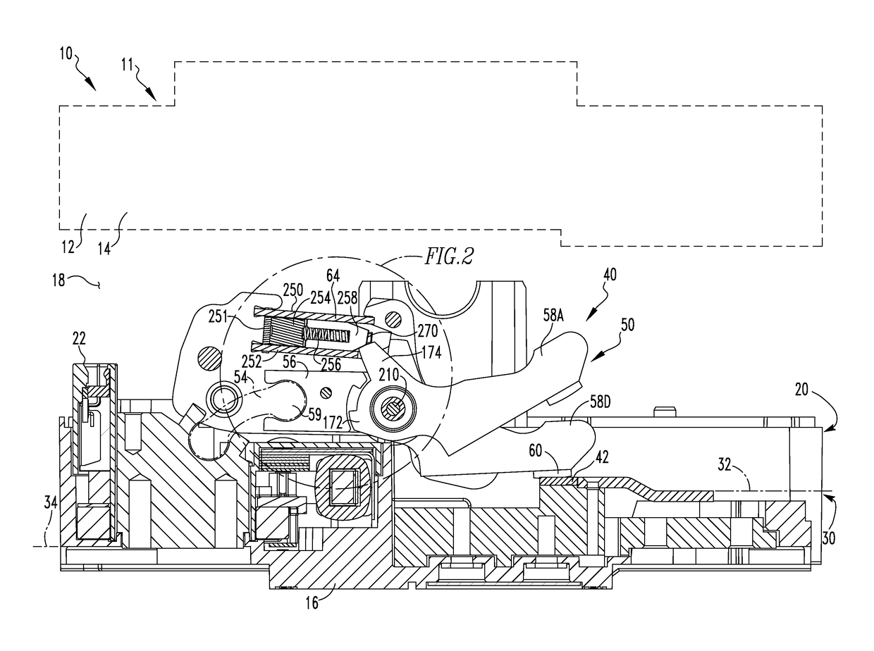
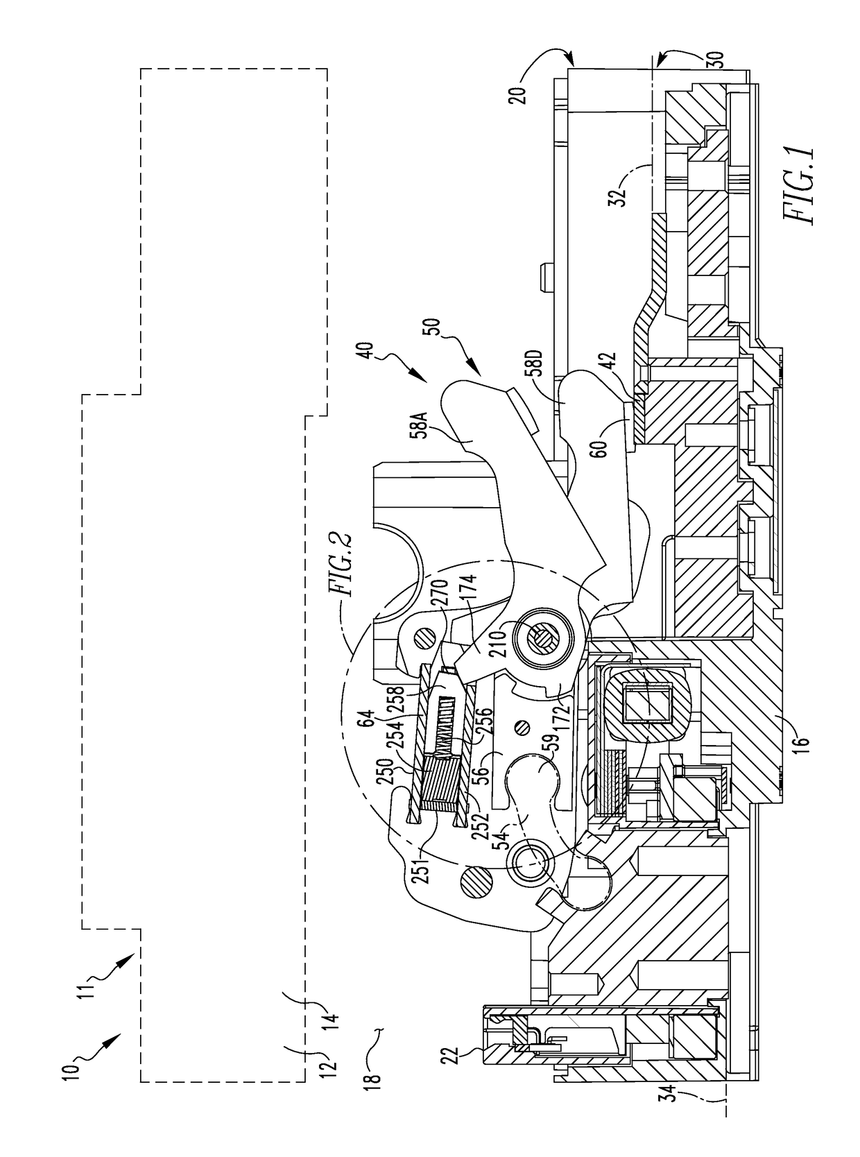
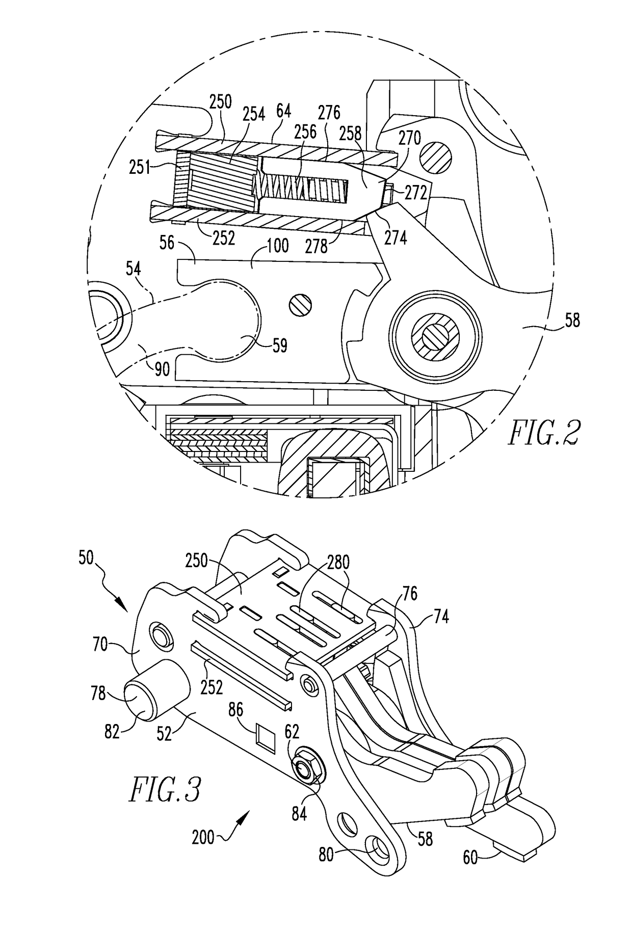
A movable contact assembly for an electrical switching apparatus is provided. The movable contact assembly includes a number of shunts, and, a carriage assembly including two sidewalls and a contact arm assembly. The carriage assembly sidewalls are disposed in a spaced relation. The contact arm assembly includes a plurality of contact arms, a number of isolation members, a number of movable contacts, and an axle. Each contact arm defines an opening, One movable contact is disposed on each contact arm. Each contact arm is rotatably coupled to the axle with the axle extending through the contact arm opening. Each isolation member is disposed adjacent at least one contact arm. Each isolation member is coupled to, and in electrical communication with the adjacent contact arm. The shunts are coupled to, and in electrical communication with, the isolation members. In this configuration, no shunt operatively engages a contact arm.

Description

BACKGROUND[0001]Field[0002]The disclosed concept relates generally to electrical switching apparatus and, more particularly, to an electrical switching apparatus such as a circuit breaker. The disclosed concept also relates to clinch joint assemblies for circuit breakers.[0003]Background Information[0004]Electrical switching apparatus, such as circuit breakers, provide protection for electrical systems from electrical fault conditions such as, for example, current overloads, short circuits, abnormal voltage and other fault conditions. Typically, circuit breakers include an operating mechanism which opens electrical contact assemblies to interrupt the flow of current through the conductors of an electrical system in response to such fault conditions. The operating mechanism is designed to rapidly open and close separable contacts. The operating mechanism is structured to be latched and thereby maintain the contacts in a closed configuration. A trip unit is structured to detect over-c...

Claims


Application Information

Patent Timeline
IPC IPC(8): H01H71/12
CPCH01H2205/002H01H71/128H01H1/226H01H1/5822
Inventor WEISTER, NATHAN J.RAKUS, PAUL RICHARDPRINCE, EDWARD A.POLLITT, WILLIAM CHARLES
Owner EATON INTELLIGENT POWER LIMITED
Features
  • Generate Ideas
  • Intellectual Property
  • Life Sciences
  • Materials
  • Tech Scout
  • Unparalleled Data Quality
  • Higher Quality Content
  • 60% Fewer Hallucinations
Learn More