Crane having an apparatus for determining the effective counterweight of said crane

a technology for determining the effective counterweight and cranes, which is applied in the direction of instruments, measuring devices, force/torque/work measurement, etc., can solve the problems of unintended inputs and crane tilting backwards, and achieve the effect of avoiding inputs that are erroneous

Active Publication Date: 2019-11-26
LIEBHERR WERK EHINGEN
View PDF12 Cites 0 Cited by
  • Summary
  • Abstract
  • Description
  • Claims
  • Application Information

AI Technical Summary

Benefits of technology

[0007]It can advantageously thus also be determined which counterweight is mounted on the crane without any intervention of a crane operator. On an additional manual input of the counterweight, a plausibility check can be made with the aid of the determined value and thus the reliability of a load torque limitation carried out on the basis of the counterweight can be improved.
[0009]It is conceivable in a further preferred embodiment that at least one spring is provided that is configured to press the piston rod at least partly into the cylinder. The spring can thus serve to preload the cylinder space permanently at a specific system pressure of, for example, 30 bar. The pressure in the cylinder space can work against the spring. The preloading of the system can achieve the advantage that the system is always filled with sufficient oil. It cannot simply empty over the course of time and, for example due to leaks, and thus impair the functionality of the apparatus. The spring furthermore creates a compensation when a cold cylinder space and / or a cylinder space filled with cold oil heats up. The risk of overpressure in the cylinder space that can destroy the cylinder is thus avoided. A possible stroke path of the piston and / or spring excursion of the spring can amount to 20 mm, for example, here.
[0013]Provision can furthermore be made in a further preferred embodiment that a safety device is provided that is configured to limit the maximum pressure in the measurement circuit to in particular 400 bar. It is hereby possible to avoid any possible damage to the measurement circuit or to prevent it.
[0014]Provision can be made in a further preferred embodiment that the piston rod is designed as spherical at its support surface. A canting or a blocking of the piston rod during the rotary movement of the receiver around the coupling designed as a pin, for example, is hereby prevented and the measurement accuracy of the apparatus is thereby improved.

Problems solved by technology

It can happen in this process that unintended error inputs take place.
In this case, the boom could be luffed up too far, which could also result in a tilting backward of the crane.

Method used


Image

  • Crane having an apparatus for determining the effective counterweight of said crane
  • Crane having an apparatus for determining the effective counterweight of said crane
  • Crane having an apparatus for determining the effective counterweight of said crane

Examples


Embodiment Construction

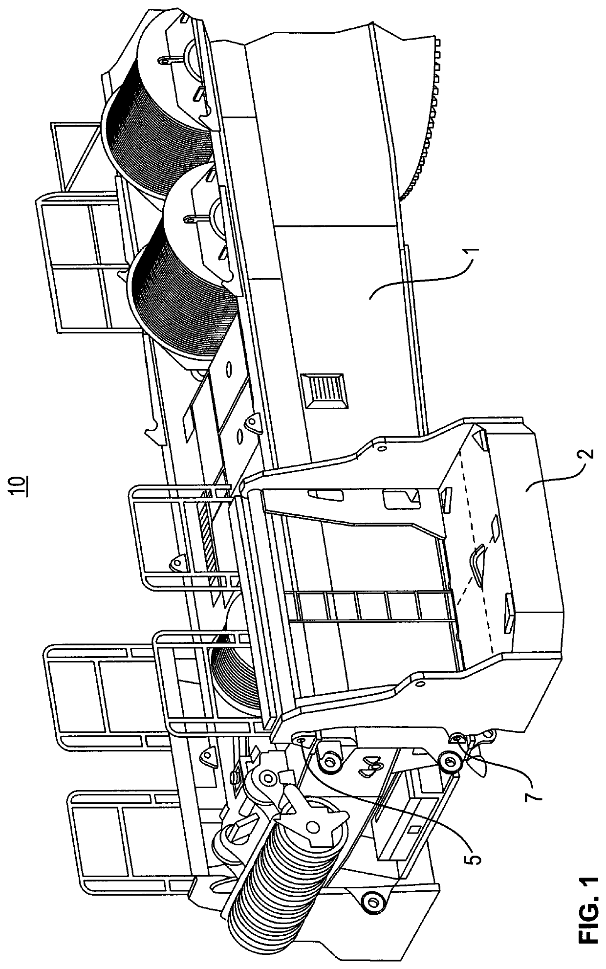
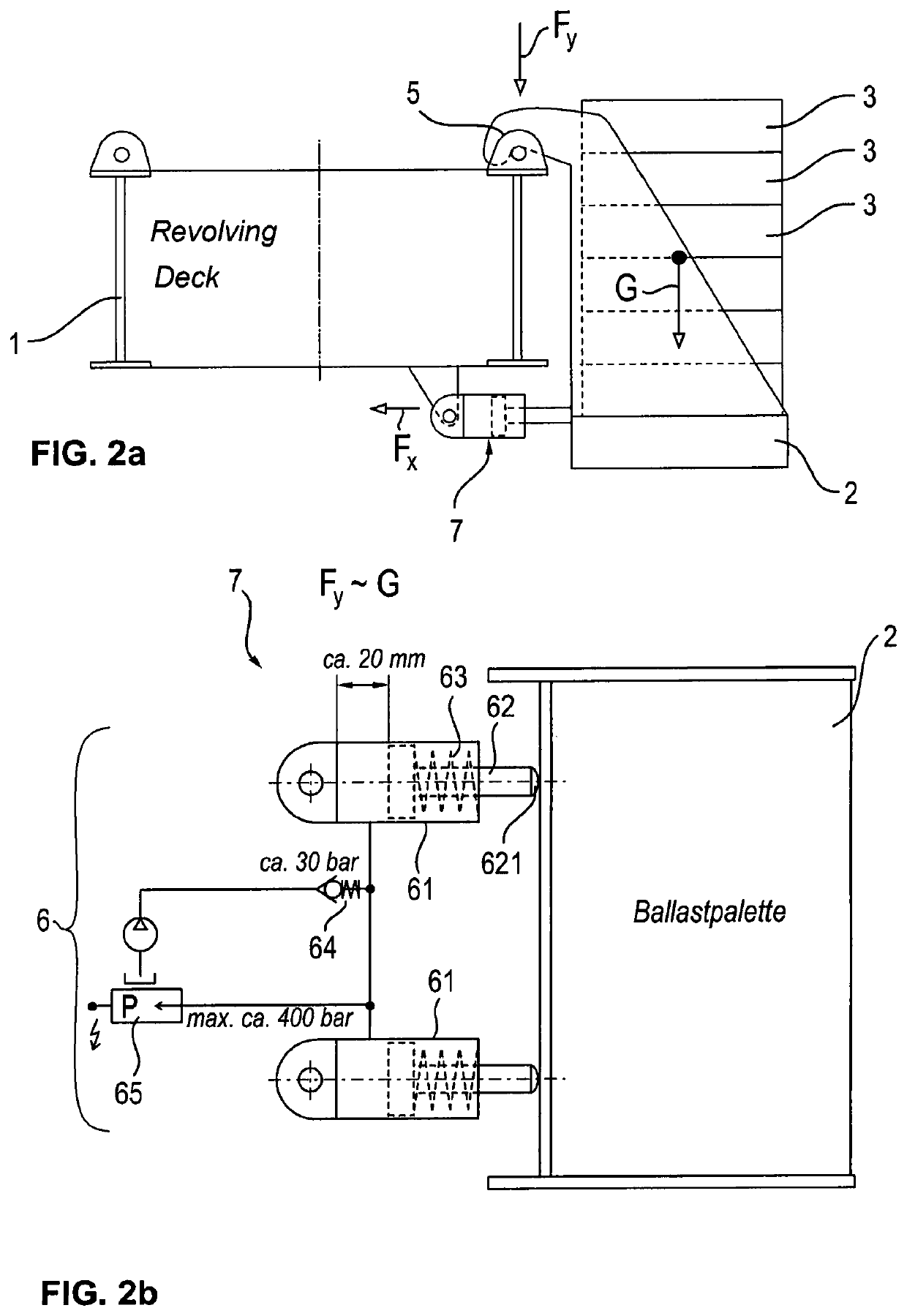
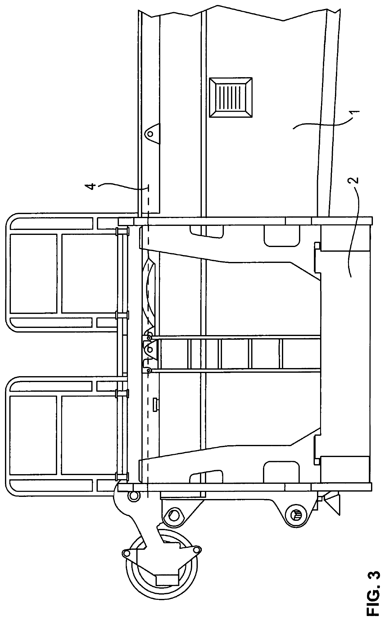
[0021]FIG. 1 shows a detail of a crane 10 in accordance with the invention having an apparatus for determining the effective counterweight that is provided at the crane 10. A receiver 2 is coupled to the remaining structure of the crane 10 here and is configured to receive one or more counterweight bodies 3 shown in FIG. 2a. The receiver 2 can here be called a ballast pallet 2 and can comprise at least one horizontal ground section on which the counterweight bodies 3 can be placed and at least one retaining section that is substantially arranged at right angles thereto and that holds the base section and the counterweight bodies 3 positionable thereon at the remaining structure of the crane 10.

[0022]A coupling 5 for a pivotable coupling of the receiver 2 with the further structure of the crane 10 can be provided in the upper region of the receiver 2. The coupling can comprise a pin 5 at the receiver 2 or at the crane 10 about which the receiver 2 is rotatably coupled to the crane 10...


PUM

PropertyMeasurementUnit
pressureaaaaaaaaaa
pressureaaaaaaaaaa
pressureaaaaaaaaaa

Abstract

The invention relates to a crane having at least one apparatus for determining the effective counterweight of said crane comprising at least one receiver for receiving at least one counterweight body; at least one coupling that is configured to pivotably couple the receiver with the further structure of the crane; and at least one abutment that is configured to limit the pivot range of the receiver.

Description

BACKGROUND OF THE INVENTION[0001]The invention relates to a crane having at least one apparatus for determining the effective counterweight of said crane comprising at least one receiver for receiving at least one counterweight body; at least one coupling that is configured to pivotably couple the receiver with the further structure of the crane; and at least one abutment that is configured to limit the pivot range of the receiver.[0002]In cranes known from the prior art, at least one counterweight provides a torque that counteracts the load borne by the crane. The applied counterweight in this respect substantially contributes to the stability of the crane.[0003]The load torque restriction devices or load torque restriction apparatus or load torque restriction methods used in cranes make use of the amount of the effective counterweight or the effective mass and the corresponding effective lever arm in calculations on the stability of the crane. It is known in this context that the ...

Claims


Application Information

Patent Timeline
Patent Type & Authority Patents(United States)
IPC IPC(8): G01L5/00G01L7/16B66C23/88B66C23/74B66C13/16
CPCB66C23/74G01L5/0061B66C23/88G01L7/163B66C13/16B66C23/72
Inventor WILLIM, HANS-DIETER
Owner LIEBHERR WERK EHINGEN
Why Eureka
Try Eureka