Switched reluctance machine and power converter

a technology of reluctance machines and power converters, applied in the direction of magnetic circuit reluctance control, control systems, electrical equipment, etc., can solve the problems of ineffective cost, inability to drive sr machines with full transistor bridges, and high power rating components, so as to reduce weight and cost, reduce the effect of iron and less copper windings

Active Publication Date: 2019-11-26
UNIV GENT
View PDF11 Cites 0 Cited by
  • Summary
  • Abstract
  • Description
  • Claims
  • Application Information

AI Technical Summary

Benefits of technology

[0032]It is an advantage of the present invention over prior art documents (such as U.S. Pat. No. 5,923,142) that less copper windings can be used and less iron, because there is not additional winding, since the windings which are already present are being used (reducing weight and cost). A drawback of the prior art system is that quite a lot of room is required to locate the additional winding, and that the stator yoke has to go around it and hence more iron is needed as well. Finally, a non-standard SRM design concept is being used.
[0033]It is an advantage of this power generator system that no position sensor is necessary.
[0034]It is an advantage of this power generator system that no controller (or signal generator) is necessary, because passive components and diodes do not need control signals, in contrast to power switches.
[0035]The amount of power generated by this machine is expected to be less than could be realized when using active components and active control (e.g. power transistors).
[0036]According to a second aspect, the present invention provides a system for converting mechanical power into electrical power, the system comprising: a switched reluctance machine having a rotor and a stator, the stator having a number of only two phase windings, the phase windings being connected in series to form a single ring structure; a power electronic circuit comprising: a means for causing a circulating current to flow in said ring structure; a number of only two legs, each of the legs comprising only passive components including two diodes connected in series between a first voltage rail and a second voltage rail, each leg having an intermediate node located between the two diodes, each intermediate node of the legs being connected to a corresponding intermediate node of the ring structure, the intermediate nodes of the ring structure being located between the two phase windings.
[0037]This is a variant of the generator circuit according to the first aspect, having only two phase windings arranged in a single ring.

Problems solved by technology

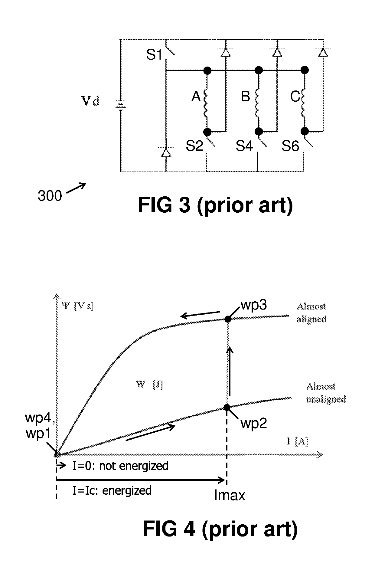
It is well known that components with a higher power rating are typically also more expensive, and in case of Switched Reluctance Motors / Generators, the power electronics can form an important fraction of the total cost (e.g. up to 50%).
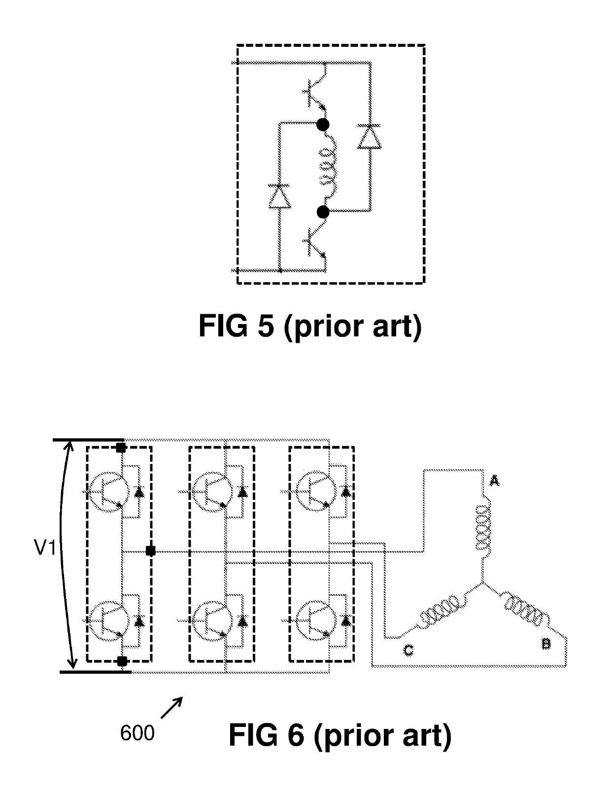
Unfortunately, these full transistor bridges cannot be used to drive SR machines, unless only one transistor of each full bridge would be used, which is very cost ineffective.
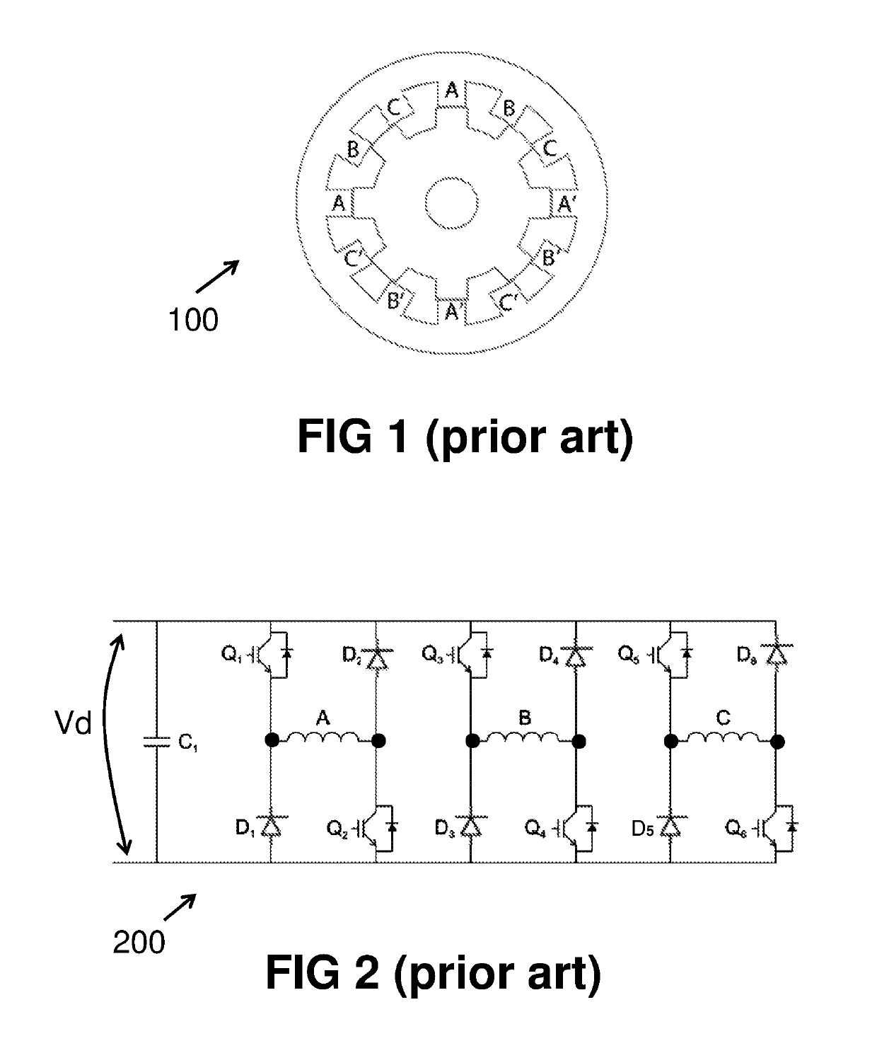
Referring back to drive circuits for SR machines, in particular to the drive circuit of FIG. 2, due to the external diodes, the switched reluctance drive circuits need two times more legs for a similar power rating, which makes the hardware more expensive.

Method used


Image

  • Switched reluctance machine and power converter
  • Switched reluctance machine and power converter
  • Switched reluctance machine and power converter

Examples


Embodiment Construction

[0106]The present invention will be described with respect to particular embodiments and with reference to certain drawings but the invention is not limited thereto but only by the claims. The drawings described are only schematic and are non-limiting. In the drawings, the size of some of the elements may be exaggerated and not drawn on scale for illustrative purposes. The dimensions and the relative dimensions do not correspond to actual reductions to practice of the invention.

[0107]Furthermore, the terms first, second and the like in the description and in the claims, are used for distinguishing between similar elements and not necessarily for describing a sequence, either temporally, spatially, in ranking or in any other manner. It is to be understood that the terms so used are interchangeable under appropriate circumstances and that the embodiments of the invention described herein are capable of operation in other sequences than described or illustrated herein.

[0108]Moreover, t...


PUM


Abstract

A generator or motor system for converting mechanical power into electrical power or vice versa, comprises: a switched reluctance machine having a rotor and a stator with a number of phase windings, the phase windings being partitioned in groups, each group comprising at least two phase windings connected in series to form a ring structure; a power electronics circuit comprising: for each ring structure, an independently controllable means for generating a circulating current in said ring structure; a number of legs, each of the legs comprising at least two diodes or switches connected in series between a first and a second voltage rail, each leg having an intermediate node located between the two diodes or switches, and connected to a corresponding intermediate node between two phase windings of a ring structure.

Description

FIELD OF THE INVENTION[0001]The invention relates to the field of Switched Reluctance machines (SRM), in particular to a system comprising a Switched Reluctance machine (SRM) such as a Switched Reluctance Motor or a Switched Reluctance Generator and a specific power converter circuit connected thereto.BACKGROUND OF THE INVENTION[0002]Switched Reluctance Machine is a term used for both Switch Reluctance Motors and Switch Reluctance Generators. The abbreviation SR stands for Switched Reluctance. The abbreviation SRM is used for SR Motors or SR Machines, the latter including SR Generators.[0003]The principle of operation of SR machines is well known in the art, although SR machines are much less used as compared to Brushless DC (BLDC) motors for example. A good reference document to SR machines is “Switched Reluctance Motors And Their Control” by T. J. E. Miller. Many references can be found on the operation of a switched reluctance motor. The document by T. J. E. Miller also shows tha...

Claims


Application Information

Patent Timeline
Patent Type & Authority Patents(United States)
IPC IPC(8): H02P25/092H02P9/40H02K19/10
CPCH02K19/10H02P9/40H02P25/092
Inventor VAN DEN BOSSCHE, ALEX
Owner UNIV GENT
Why Eureka
Try Eureka