
Drone with dynamic antenna diversity

a dynamic antenna and drone technology, applied in the field of remote piloting, can solve the problems of significant data volumes, risk of sporadic loss affecting exchanged data and commands, and the regulation constraints applicable to the rf communication system, and achieve the effect of minimizing the signal/noise ratio and maximizing the data ra

Active Publication Date: 2019-11-26
PARROT
View PDF6 Cites 4 Cited by
  • Summary
  • Abstract
  • Description
  • Claims
  • Application Information

AI Technical Summary

Benefits of technology

The patent text describes a drone with a dynamic reconfiguration of the antenna network that allows for better RF transmission even when the drone moves and the environment changes. This means that the drone can always have the best signal quality and minimize signal interference, ensuring high data rates and reliable communication. The drone has a digital controller circuit, RF transmitter stage with fixed antennas, and a baseband processor circuit to deliver an RF signal for transmission.

Problems solved by technology

Moreover, the transmitted data volumes are significant, in particular due to the very high video rate need of the downlink.
De facto, any degradation of quality of the radio link will have an impact on the transmission quality and on the radio range, with a risk of sporadic loss affecting the exchanged data and commands.
A significant limitation lies in the regulation constraints applicable to the RF communication systems such as the Wi-Fi communication systems used by the drones (or any other RF power transmitter system).
The difficulty comes from the fact that, in the case where several transmitters deliver simultaneously an RF signal, respecting the regulatory radiated power threshold imposes to reduce the own RF power of each active transmitter so that the total RF power wholly radiated remains lower than the imposed threshold (36 dBm in the hereinabove example).

Method used


Image

  • Drone with dynamic antenna diversity
  • Drone with dynamic antenna diversity
  • Drone with dynamic antenna diversity

Examples


Embodiment Construction

[0030]An exemplary embodiment of the device of the invention will now be described.

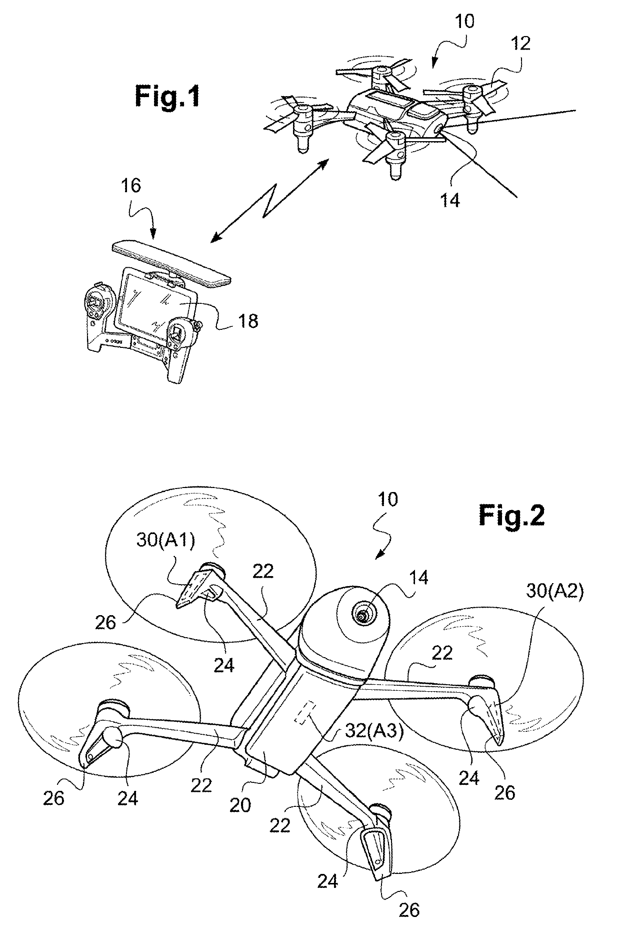
[0031]In FIG. 1, the reference 10 generally denotes a drone that has four coplanar rotors 12, whose motors are piloted independently from each other by an integrated navigation and attitude control system. A front-view camera 14 is provided, allowing obtaining an image of the scene towards which the drone is directed. The drone 10 is piloted by a user by means of a distant remote-control device 16, hereinafter called “remote control”, provided with a screen 18 configured to display the image captured by the camera 14 of the drone. The remote control 16 is for example the Skycontroller model from Parrot, on which has been mounted a smartphone (pocket mobile terminal) or a touch-screen multimedia digital tablet of the standard type, not modified except the loading of a specific applicative software (such as the mobile application AR Free Flight from Parrot) to control the piloting of the drone 10 and th...


PUM

PropertyMeasurementUnit
altitudeaaaaaaaaaa
distanceaaaaaaaaaa
distanceaaaaaaaaaa

Abstract

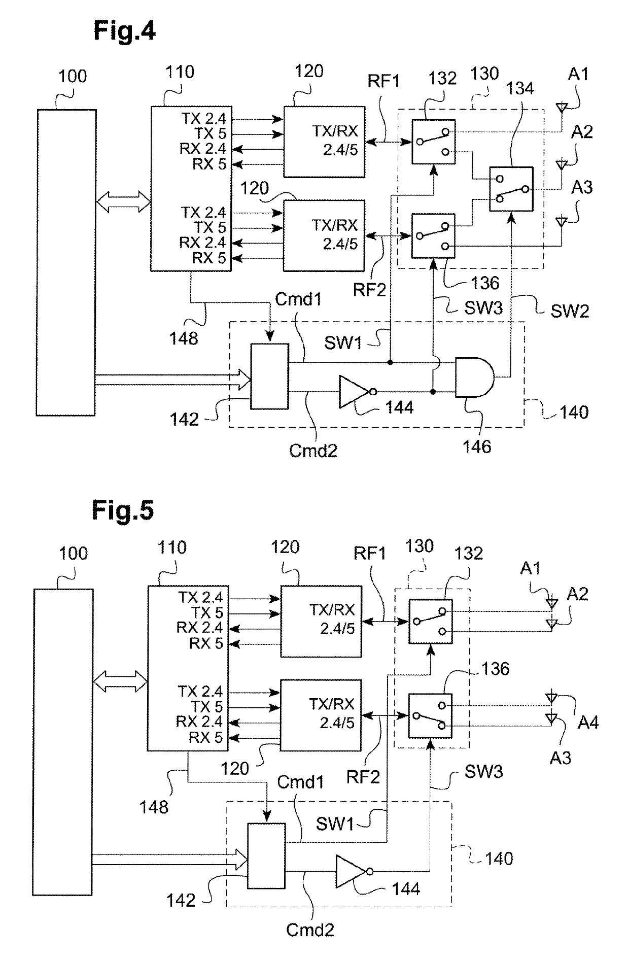
The drone comprises M antennas, with in particular two offset antennas located symmetrically at the ends of two arms for the connection to the propulsion units (24), and a ventral antenna under the drone body. The radio transmission is operated simultaneously on N similar RF channels, with 2≤N<M. An antenna switching circuit couples selectively each of the N RF channels to N antennas out of the M antennas according to a plurality of different coupling schemes, dynamically through a piloting logic selecting one of the coupling schemes. The selection is operated as a function of a signal delivered by the drone-borne microprocessor, as a function of the flight and signal transmission conditions, determined at a given instant.

Description

CROSS-REFERENCE TO RELATED APPLICATIONS[0001]This application claims priority under 35 U.S.C. § 119(a) to French Patent Application Serial Number 1670789, filed Dec. 27, 2016, the entire teachings of which are incorporated herein by reference.BACKGROUND OF THE INVENTIONField of the Invention[0002]The invention relates to the remote piloting of motorized devices, hereinafter generally referred to as “drones”, and more precisely, the radio-communication antennas used by drones for the remote piloting thereof.Description of the Related Art[0003]A typical example of consumer flying drone is the BEBOP™ drone manufactured by Parrot, S.A. of Paris, France, which is a rotary-wing drone of the quadricopter type. Another example of a consumer flying drone is the DISCO™ drone also manufactured by Parrot, S.A. of Paris, France, which a fixed-wing drone of the sail-wing type. Yet another type of drone is the JUMPING SUMO™ also manufactured by Parrot, S.A. of Paris, France. However, unlike the BE...

Claims


Application Information

Patent Timeline
Patent Type & Authority Patents(United States)
IPC IPC(8): H04B7/0404B64D47/08G05D1/00B64C39/02H04L5/14H04B7/06H04B7/0426
CPCH04B7/0404B64C39/024B64D47/08H04L5/1423H04B7/0602G05D1/0038B64C2201/146B64C2201/027H04B7/0426B64C2201/108G08C17/02H04B7/0413B64U2201/20B64U20/83B64U10/14G08C2201/60B29L2031/24B29K2223/12B29L2031/7739B29K2067/00B29K2077/00B29C49/04B29C49/4817B29C2049/4807B29C2049/6072G08C2201/93B29L2023/004G08C2201/91G08C2201/63B29L2031/30B29C49/4245A63H27/00
Inventor GASNIER, ERICPROD'HOMME, RAPHAËL
Owner PARROT
Learn More