Radar imaging system

a technology of radar imaging and imaging system, applied in the field of radar imaging system, can solve the problems of limited performance, long acquisition time, and reduced performance when imaging moving targets

Active Publication Date: 2019-12-10
QINETIQ LTD
View PDF22 Cites 1 Cited by
  • Summary
  • Abstract
  • Description
  • Claims
  • Application Information

AI Technical Summary

Benefits of technology

[0017]The plurality of airborne carriers form at least one large effective antenna aperture, the aperture comprising of the combination of the individual antenna elements mounted on each of the carriers. This may be located at a height above ground level to provide high angular resolution radar imagery. This aspect of the present invention provides a simplified aperture yet provides the capabilities for very complex, fast processing of the radar echoes to produce images of high resolution. The or each aperture may be located so as to provide a different field of view with respect to the target to reduce shadows in the final image. High range resolution may also achieved by configuring the radar transmitter to transmit a wide bandwidth (for example up to 1 GHz) chirped pulse, and by compressing this pulse either using computer resource in the airborne carriers or within a remote basestation. The airborne carriers are positioned in close proximity to form an array (swarm). The airborne carriers function as radar receivers and work in conjunction with a radar transmitter. The airborne carriers may work in conjunction with a radar transmitter in a bistatic configuration.
[0032]The plurality of airborne carriers may be networked. This then allows data, such as location data or radar echo data, to be transferred between the carriers. This can be used to improve the efficiency of the data connection between the carriers and the base station. For example, a given carrier may be able to pass data relating to the position, or data concerning radar echoes, received by another carrier, to the base station, to decrease the network load on the base station.

Problems solved by technology

Ultra-high accuracy tracking and high-resolution imagery to support target classification and recognition at long range is currently provided by high-resolution electro-optic devices, with the drawback of very limited performance in adverse weather conditions, or by Synthetic Aperture Radar (SAR) techniques which have the drawback of lengthy acquisition times and reduced performance when imaging moving targets.
However, the effects of turbulence and positional errors of the individual UAVs have a dramatic impact on the accuracy and resolution of the resulting image.

Method used


Image

  • Radar imaging system
  • Radar imaging system
  • Radar imaging system

Examples


Embodiment Construction

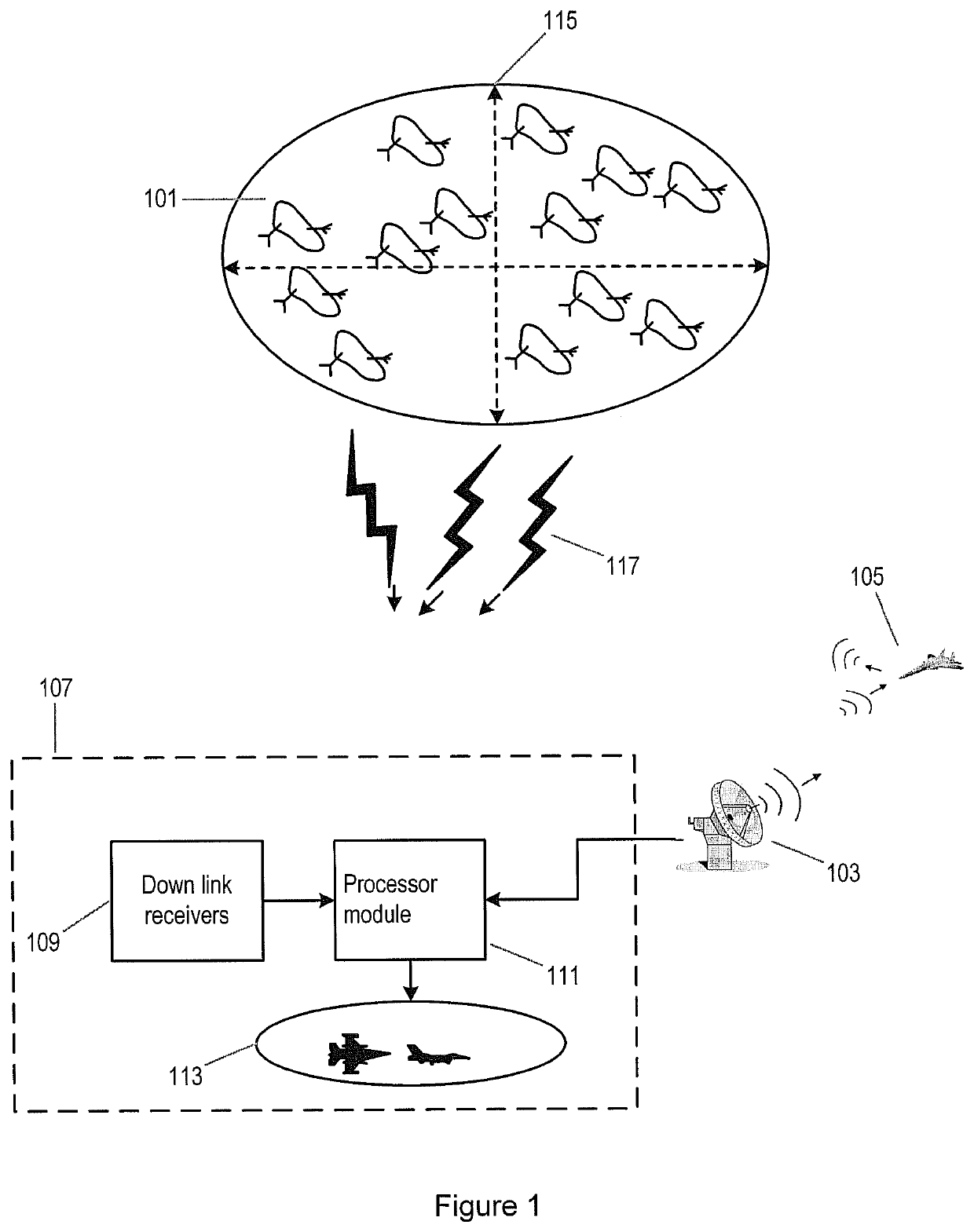
[0045]The system according to an embodiment is shown in FIG. 1. The system comprises a plurality of airborne carriers 101, such as unmanned aerial vehicles (UAVs). Each airborne carrier comprises a radar receiver and communications equipment (described in more detail with reference to FIG. 3). The system includes a radar system 103 and a base-station 107. The base-station 107 comprises at least one downlink transceiver 109, a processor module 111 and a display module 113. The radar system 103 comprises a transmitter and receiver, and is capable of locating and tracking targets independently. The transmitter of the radar 103 is used to illuminate the target both for its own receiver, and also for the receivers in the airborne carriers 101.

[0046]The plurality of airborne carriers 101 are substantially similar, are miniature and may comprise rotary or fixed wing airborne carriers 101. The plurality of airborne carriers are positioned in close proximity in a predefined area to form an a...


PUM


Abstract

Some embodiments are directed to a radar imaging system that includes a radar transmitter configured to transmit radar at a target; an aperture including an array of physically independent airborne carriers, each of the carriers configured to receive radar echoes from the target; and a base station, which may be located at ground level, in communication with each of the airborne carriers to receive the radar echoes and determine an image of the target from the received radar echoes.

Description

[0001]This application is a national phase filing under 35 C.F.R. § 371 of and claims priority to PCT Patent Application No. PCT / EP2013 / 072860, filed on Nov. 1, 2013, which claims the priority benefit under 35 U.S.C. § 119 of British Patent Application No. 1219732.3 filed on Nov. 2, 2012, which are hereby incorporated in their entireties by reference.FIELD OF THE INVENTION[0002]The present invention relates to a radar imaging system. In particular, but not exclusively, it relates to an aperture for a radar imaging system comprising a swarm of miniature airborne carriers (or unmanned aerial vehicles (UAVs)).BACKGROUND TO THE INVENTION[0003]Ultra-high accuracy tracking and high-resolution imagery to support target classification and recognition at long range is currently provided by high-resolution electro-optic devices, with the drawback of very limited performance in adverse weather conditions, or by Synthetic Aperture Radar (SAR) techniques which have the drawback of lengthy acquis...

Claims


Application Information

Patent Timeline
Patent Type & Authority Patents(United States)
IPC IPC(8): G01S13/90G01S13/00G01S7/00G01S5/06
CPCG01S7/003G01S13/904G01S13/90G01S5/06G01S13/003G01S13/9058
Inventor DAWBER, WILLIAM NICHOLASPEARSON, GARY STEVEN
Owner QINETIQ LTD
Why Eureka
Try Eureka