Open flame control system for weed control

a technology of open flame control and weed control, which is applied in the direction of weed killers, combustion types, lighting and heating apparatuses, etc., can solve the problems of out-of-control fires, inefficient and hazardous open flame burners and torches currently used for weed control

Active Publication Date: 2019-12-24
PRULL GREGORY G
View PDF3 Cites 0 Cited by
  • Summary
  • Abstract
  • Description
  • Claims
  • Application Information

AI Technical Summary

Benefits of technology

[0005]It is an object of the present invention to provide a more economical, flexible, adaptive, and light weight open flame control system for torches and burners used for weed control.
[0008]The components are engineered both individually and in relationship to each other so they will perform successfully in a coordinated manner and provide cost-effective results for specific uses or applications. This open flame control system is also “scalable”, enabling the development of tools appropriate for application to small or large weed control operations.
[0010]The simplest form of the surrounding structure involves a tubular structure having at least partially solid or at least partially porous walls that contain and direct the flame(s) and the flow of hot gases toward the ground, preventing or limiting their full expansion and impact until they exit the containing tube. The cross-section of the tubular structure may be circular, oval, square, rectangular, etc. Preferably the tubular structure is substantially cylindrical. This form of the device helps prevent off target impacts and improves fuel efficiency while also providing the user with the ability to allow the flame and hot gases to expand in all directions a they exit the tube, thereby maximizing the “footprint” or impact area and making it easy to apply the tool effectively.
[0011]This control system is useful when there is a relatively large area with weeds to be treated and it allows the device to be held above the ground surface so the applicator can cover more ground with less effort than with the more complex design of the control system which requires maintenance of close proximity to the surface of the ground. The structure surrounding the burner(s) or torch(es) may be shaped (e.g., round, oval, etc.) to help influence the ground impact for a specific need or purpose. The length of the structure is coordinated with the size of the burner(s) or torch(es) and the length of the flame they produce and will be less than the focal length of the flame to allow the device to be held above the ground while providing maximum impact. One or more struts are used to hold the structure n the proper location relative to the position of the burner(s) or torch(es) and to provide a means to connect the surrounding structure to the burner(s) or torch(es) and to the fuel inlet supplying them. Additional struts or supporting elements may be utilized when the walls of the “tube” are constructed from thin solid material(s) or those made of mesh material(s).
[0012]The second and more complex form of the device has a superstructure with an open framework or basket which allows the combined use of other components that provide the user with greater control of the flame and hot gases exiting from the burner(s) or torch(es), a level of control which is not available from the more simple device.

Problems solved by technology

However, open flame burners and torches currently used for weed control are inefficient and hazardous.
They are fuel intensive and unwanted smoke, out-of-control fires, as well as damage to desirable plants including horticultural plantings and agricultural crops, are a routine occurrence.

Method used


Image

  • Open flame control system for weed control
  • Open flame control system for weed control
  • Open flame control system for weed control

Examples


Embodiment Construction

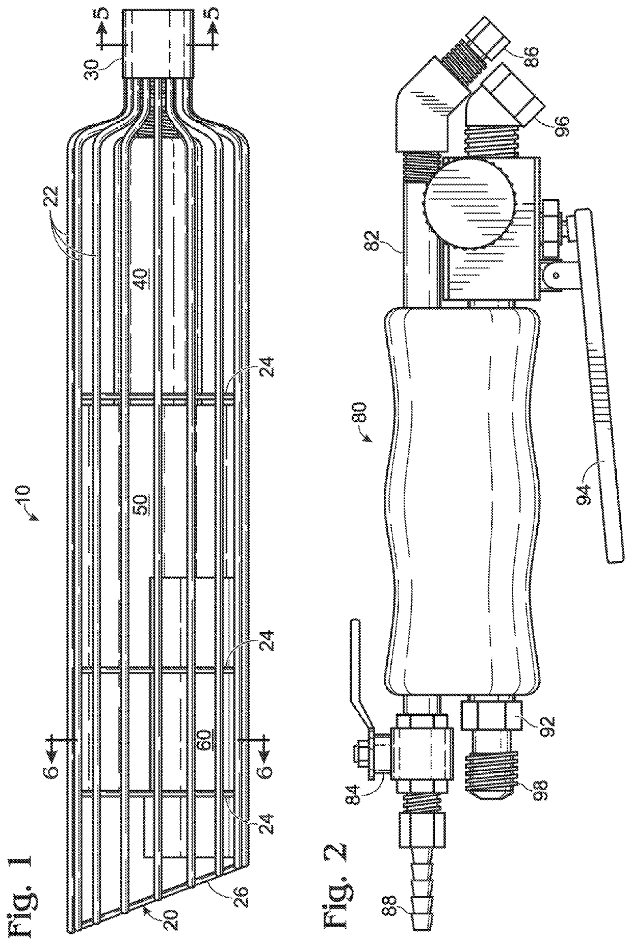
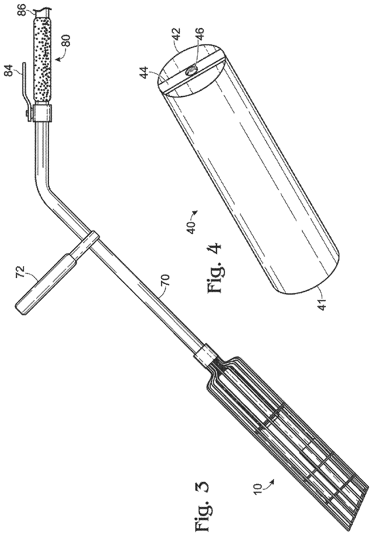
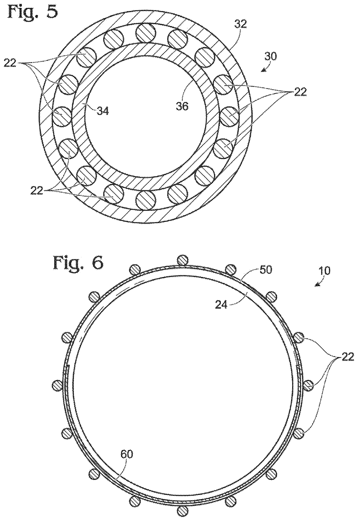
[0026]The flame control device 10 is comprised of an open superstructure or basket 20 having a framework including a plurality of longitudinal struts 22. Struts 22 are held in place by attachment to a plurality of intermediate hoops 24 and a bottom hoop 26. Struts 22 vary in length to provide an angled bottom portion wherein the plane of bottom hoop 26 is at an angle to the longitudinal axis of device 10, as shown. The back side portion of device 10 is shown at the bottom of FIGS. 1 and 6 (the side with the shorter struts 22) and the front side portion of device 10 is that portion shown at the top of FIGS. 1 and 6 (the side with the longer struts 22).

[0027]A hub 30 is located at the upper end of typical device 10 and has an outer body 32 and an inner body 34. The upper ends of struts 22 are bent inwardly and upwardly for insertion into and attachment to the space between outer body 32 and inner body 34 of hub 30, as can be seen in FIG. 5. The inner wall 36 of inner body 34 is thread...


PUM


Abstract

An open flame control device for weed control. The device includes a substantially cylindrical basket having an open framework including a plurality of substantially equally spaced-apart longitudinal struts attached to a plurality of hoops, struts being inwardly and upwardly bent at the upper end of the basket. A hub is located at the upper end of the basket and is attached to the inwardly and upwardly bent struts. An open flame burner is located within the basket and attached to the hub. A porous metal fabric liner surrounds the inside of the basket and is attached thereto. A metal flame reflector is located at the lower end of the basket and occupies the back side portion of the basket. Means are provided for communicating the open flame burner with a supply of propane. Optionally, means are provided to supply water to the bottom of the basket.

Description

CROSS REFERENCE TO RELATED APPLICATIONS[0001]This application claims the benefit of Provisional Patent Application Ser. No. 61 / 688,656 filed May 18, 2012, the entire contents of which are hereby incorporated by reference.BACKGROUND OF THE INVENTION[0002]The present invention relates to an open flame control system for weed control primarily by use of hand held devices, but also, for some applications, of larger, mechanized equipment.[0003]The use of herbicides and other chemicals to control weeds has generated much environmental concern.[0004]One alternative to the use of herbicides and other chemicals to control weeds is the use of open flame burners and torches. However, open flame burners and torches currently used for weed control are inefficient and hazardous. They are fuel intensive and unwanted smoke, out-of-control fires, as well as damage to desirable plants including horticultural plantings and agricultural crops, are a routine occurrence.SUMMARY OF THE INVENTION[0005]It i...

Claims


Application Information

Patent Timeline
Patent Type & Authority Patents(United States)
IPC IPC(8): F23C7/00A01M21/04F23D14/58
CPCF23D14/58A01M21/04A01M15/00F41H9/02
Inventor PRULL, GREGORY G.
Owner PRULL GREGORY G
Why Eureka
Try Eureka