Supercharge Your Innovation With Domain-Expert AI Agents!

Dust collector for electric power tool and electric power tool

a technology of electric power tools and dust collectors, which is applied in the direction of portable power tools, metal-working machine components, manufacturing tools, etc., can solve the problems of poor operability at a narrow position, less likely to provide accuracy in the right-left direction, and looseness to reduce slidingability

Active Publication Date: 2019-12-24
MAKITA CORP
View PDF31 Cites 2 Cited by
  • Summary
  • Abstract
  • Description
  • Claims
  • Application Information

AI Technical Summary

Benefits of technology

The design enhances operability in tight spaces, reduces the risk of damage, ensures accurate guidance, and maintains dust collection efficiency even with increased dust accumulation, while the telescopic structure allows for a compact form factor without upsizing the main body.

Problems solved by technology

Then, a dimension increases in a right-left direction, thus causing poor operability at a narrow position.
Furthermore, since the guiding portion and the guided portion are arranged at positions apart from one another on right and left of the sliding portion, it is less likely to provide accuracy in the right-left direction, thus causing a tangle and a looseness to decrease slidability in some cases.

Method used


Image

  • Dust collector for electric power tool and electric power tool
  • Dust collector for electric power tool and electric power tool
  • Dust collector for electric power tool and electric power tool

Examples


Embodiment Construction

[0075]The following describes embodiments of the disclosure based on the drawings.

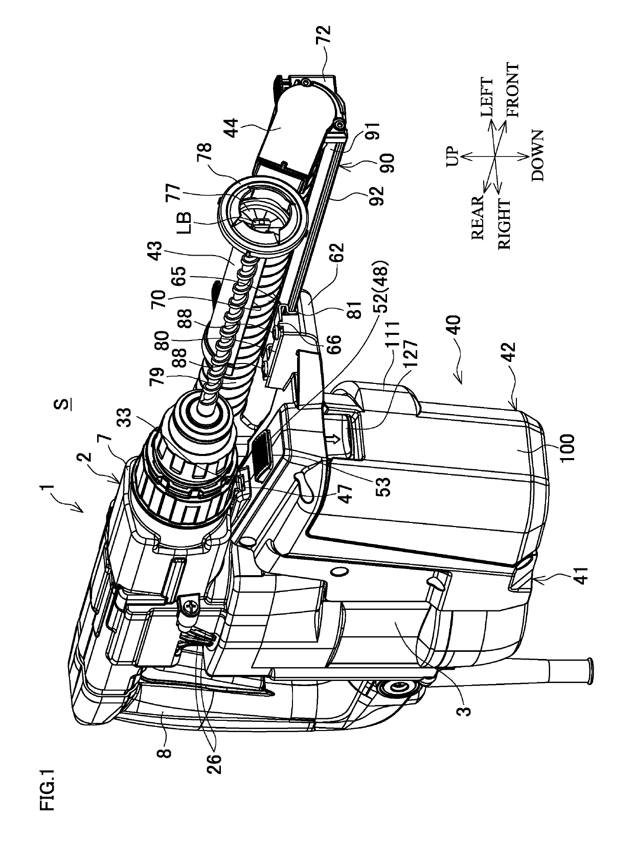
[0076]FIGS. 1 to 4 illustrate an exemplary dust collection system S where a dust collector for an electric power tool (hereinafter simply referred to as “a dust collector”) 40 is installed on a hammer drill 1 as an electric power tool. FIG. 1 is a perspective view from a front, FIG. 2 is a side view, FIG. 3 is a plan view, and FIG. 4 is a front view.

[0077]As also illustrated in FIG. 5 and FIG. 8, the hammer drill 1 internally includes a motor housing 3, which houses a motor 4 with an output shaft 5 disposed upward, in a vertical direction on a front lower portion of a main body housing 2. Above the motor housing 3, the hammer drill 1 internally includes a gear housing 6 that houses a crank mechanism and a rotation mechanism. The hammer drill 1 includes a front housing 7, which houses a tool holder disposed forward, assembled on the front of the main body housing 2, and includes a handle housing 8, whic...


PUM

PropertyMeasurementUnit
drilling depthaaaaaaaaaa
diameteraaaaaaaaaa
projection lengthaaaaaaaaaa

Abstract

A dust collector for an electric power tool includes a main body case, a tubular sliding portion, and a dust collection portion. The main body case is mountable to an electric power tool. The tubular sliding portion is disposed on the main body case. The sliding portion includes a nozzle on a front end thereof. The nozzle includes a suction opening. The dust collection portion is configured to accumulate dust suctioned from the nozzle. The sliding portion includes a guided portion supported by a guiding portion disposed on the main body case. The guided portion is supported slidably in a front-rear direction, and the guiding portion and the guided portion are disposed in a region on a half side with respect to a line on a cross section passing through a center of the sliding portion.

Description

BACKGROUND[0001]This application claims the benefits of Japanese Patent Application Numbers 2017-005298 filed on Jan. 16, 2017, 2017-005299 filed on Jan. 16, 2017, and 2017-005300 Jan. 16, 2017, the entirety of which is incorporated by reference.TECHNICAL FIELD[0002]This disclosure relates to a dust collector for electric power tool mounted on an electric power tool such as an electric drill and a hammer drill, and an electric power tool on which the dust collector is installed.RELATED ART[0003]An electric power tool such as an electric drill and a hammer drill sometimes includes a dust collector that collects dust generated from a workpiece in a drilling work and similar work. As the dust collector for the electric power tool, a dust collector disclosed in Japanese Patent No. 5707293 has been known. Here, the dust collector includes a housing mounted on a housing of the electric power tool, the housing of the dust collector has a front end on which a ventilation member (a slide pip...

Claims


Application Information

Patent Timeline
Patent Type & Authority Patents(United States)
IPC IPC(8): B23Q11/00B23B47/34
CPCB23B47/34B23Q11/0046Y10T408/50B23B2260/058B23Q11/0071B25F5/00
Inventor YOSHIKANE, KIYONOBU
Owner MAKITA CORP
Features
  • R&D
  • Intellectual Property
  • Life Sciences
  • Materials
  • Tech Scout
  • Unparalleled Data Quality
  • Higher Quality Content
  • 60% Fewer Hallucinations
Learn More