Supercharge Your Innovation With Domain-Expert AI Agents!

Overheat detection circuit, overheat protection circuit, and semiconductor device

a technology of overheat protection and detection circuit, which is applied in the direction of emergency protective circuit arrangement, heat measurement, instruments, etc., can solve the problems of difficult adjustment, and achieve the effect of easy adjustment of manufacturing variation

Active Publication Date: 2019-12-24
ABLIC INC
View PDF5 Cites 0 Cited by
  • Summary
  • Abstract
  • Description
  • Claims
  • Application Information

AI Technical Summary

Benefits of technology

The present invention provides an overheat detection circuit that can easily detect and adjust manufacturing variation. The circuit has high detection precision and includes two resistors with the same temperature characteristics. This makes it easy to adjust the circuit and ensures accurate detection of overheating.

Problems solved by technology

This has made such adjustment extremely difficult.

Method used


Image

  • Overheat detection circuit, overheat protection circuit, and semiconductor device
  • Overheat detection circuit, overheat protection circuit, and semiconductor device
  • Overheat detection circuit, overheat protection circuit, and semiconductor device

Examples


first embodiment

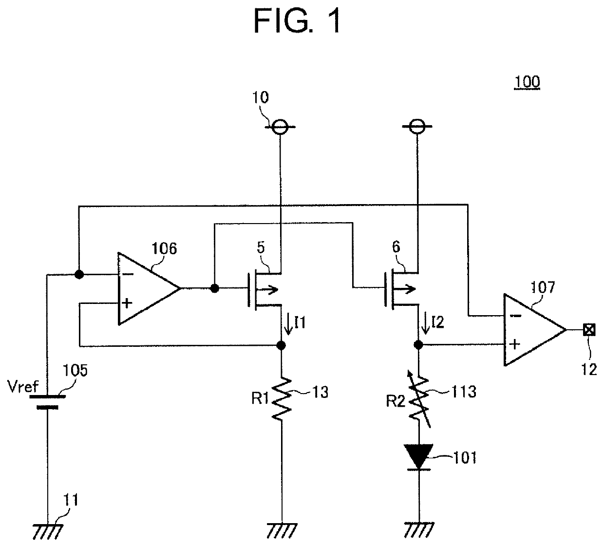
[0023]FIG. 1 is an illustration of an overheat detection circuit 100 according to the present invention.

[0024]The overheat detection circuit 100 is configured in the following manner.

[0025]A voltage (hereinafter referred to as Vref) output from a reference voltage source 105 is input to an inverting input terminal of a differential amplifier 106. One end of a resistor 13 and a drain of a P-channel transistor 5 are connected to a non-inverting input terminal of the differential amplifier 106. An output terminal of the differential amplifier 106 is connected to a gate of the P-channel transistor 5 and a gate of a P-channel transistor 6. A source of the P-channel transistor 5 is connected to a power supply terminal 10. Another end of the resistor 13 is connected to a ground terminal 11. A source of the P-channel transistor 6 is connected to the power supply terminal 10, and a drain thereof is connected to one end of an adjustable resistor 113 that has an adjustable resistance value. An...

second embodiment

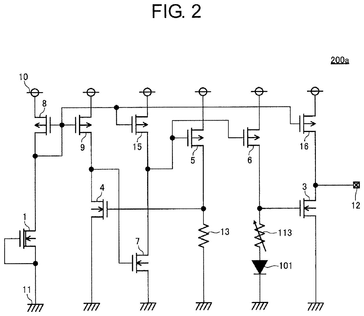
[0032]FIG. 2 is a circuit diagram for illustrating an overheat detection circuit 200a as a first example of an overheat detection circuit according to the present invention.

[0033]The overheat detection circuit 200a is configured in the following manner.

[0034]A drain of an N-channel depletion transistor 1 is connected to a drain and a gate of a P-channel transistor 8, a gate of a P-channel transistor 9, a gate of a P-channel transistor 15, and a gate of a P-channel transistor 16. A gate and a source of the N-channel depletion transistor 1 are connected to the ground terminal 11.

[0035]A source of the P-channel transistor 8 is connected to the power supply terminal 10.

[0036]A drain of the P-channel transistor 9 is connected to a drain of an N-channel transistor 4 and a gate of an N-channel transistor 7. A source of the P-channel transistor 9 is connected to the power supply terminal 10.

[0037]A source of the N-channel transistor 4 is connected to the ground terminal 11, and a gate there...


PUM

PropertyMeasurementUnit
temperatureaaaaaaaaaa
resistanceaaaaaaaaaa
voltageaaaaaaaaaa

Abstract

Provided is an overheat detection circuit capable of easily adjusting a detection temperature of the overheat detection circuit. The overheat detection circuit includes: a first resistor; a second resistor, which has the same temperature characteristics with the first resistor, and has an adjustable resistance value; and a heat sensitive element connected to one end of the second resistor, in which a first current, which is based on a first voltage, is supplied to the first resistor, a current, which is proportional to the first current, is supplied to the second resistor so that a second voltage is generated at another end of the second resistor, and when the first voltage and the second voltage are compared, a result of the comparison is output as an overheat detection signal.

Description

RELATED APPLICATIONS[0001]This application claims priority under 35 U.S.C. § 119 to Japanese Patent Application No. 2015-219614 filed on Nov. 9, 2015, the entire content of which is hereby incorporated by reference.BACKGROUND OF THE INVENTION[0002]1. Field of the Invention[0003]The present invention relates to an overheat detection circuit, an overheat protection circuit including the overheat detection circuit, and a semiconductor device including the overheat protection circuit.[0004]2. Description of the Related Art[0005]FIG. 6 is a circuit diagram for illustrating a related-art overheat detection circuit 600.[0006]The related-art overheat detection circuit 600 is configured in the following manner.[0007]A constant current source 608 is connected between a power supply terminal 60 and an anode of a diode 601, to thereby output a constant current JO.[0008]A cathode of the diode 601 is connected to one end of an adjustable resistor 613, and another end of the adjustable resistor 61...

Claims


Application Information

Patent Timeline
Patent Type & Authority Patents(United States)
IPC IPC(8): G01K7/16
CPCG01K7/16G01K7/01G01K3/005G01K7/20H02H5/04H01L27/0248
Inventor NAKASHIMO, TAKAO
Owner ABLIC INC
Features
  • R&D
  • Intellectual Property
  • Life Sciences
  • Materials
  • Tech Scout
  • Unparalleled Data Quality
  • Higher Quality Content
  • 60% Fewer Hallucinations
Learn More