
Electric power steering apparatus

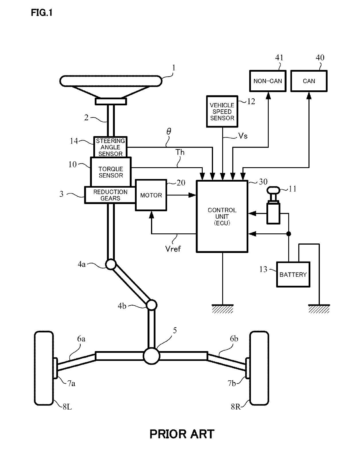
a technology of electric power steering and steering shaft, which is applied in the direction of electric generator control, dynamo-electric converter control, dynamo-electric gear control, etc., can solve the problems of affecting the steering follow-up performance and steering feeling in turn-back steering, distorted current waveform, and poor steering feel of turn-back steering, etc., to suppress the effect of rippl

Active Publication Date: 2020-01-07
NSK LTD
View PDF21 Cites 2 Cited by
  • Summary
  • Abstract
  • Description
  • Claims
  • Application Information

AI Technical Summary

Benefits of technology

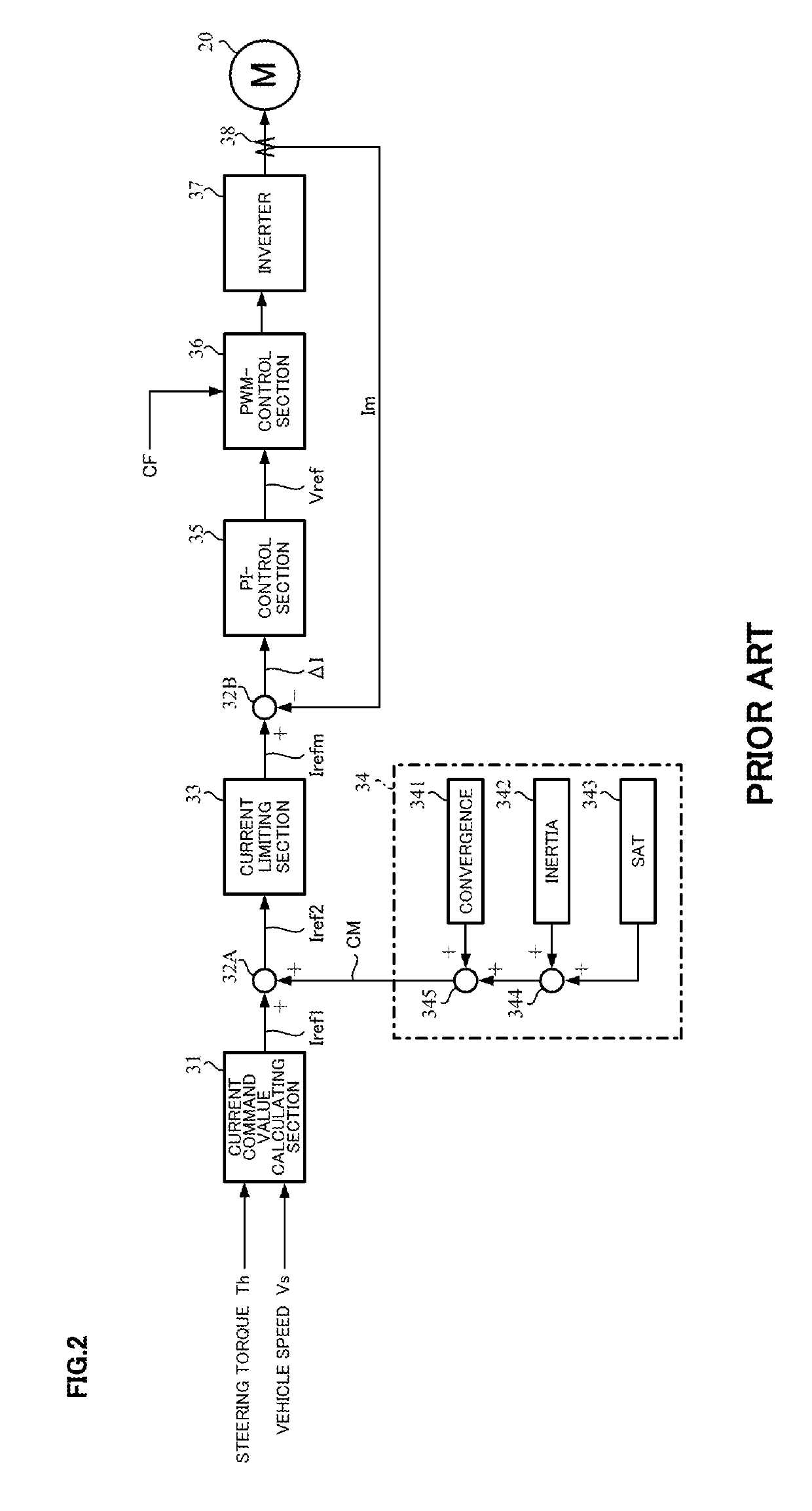
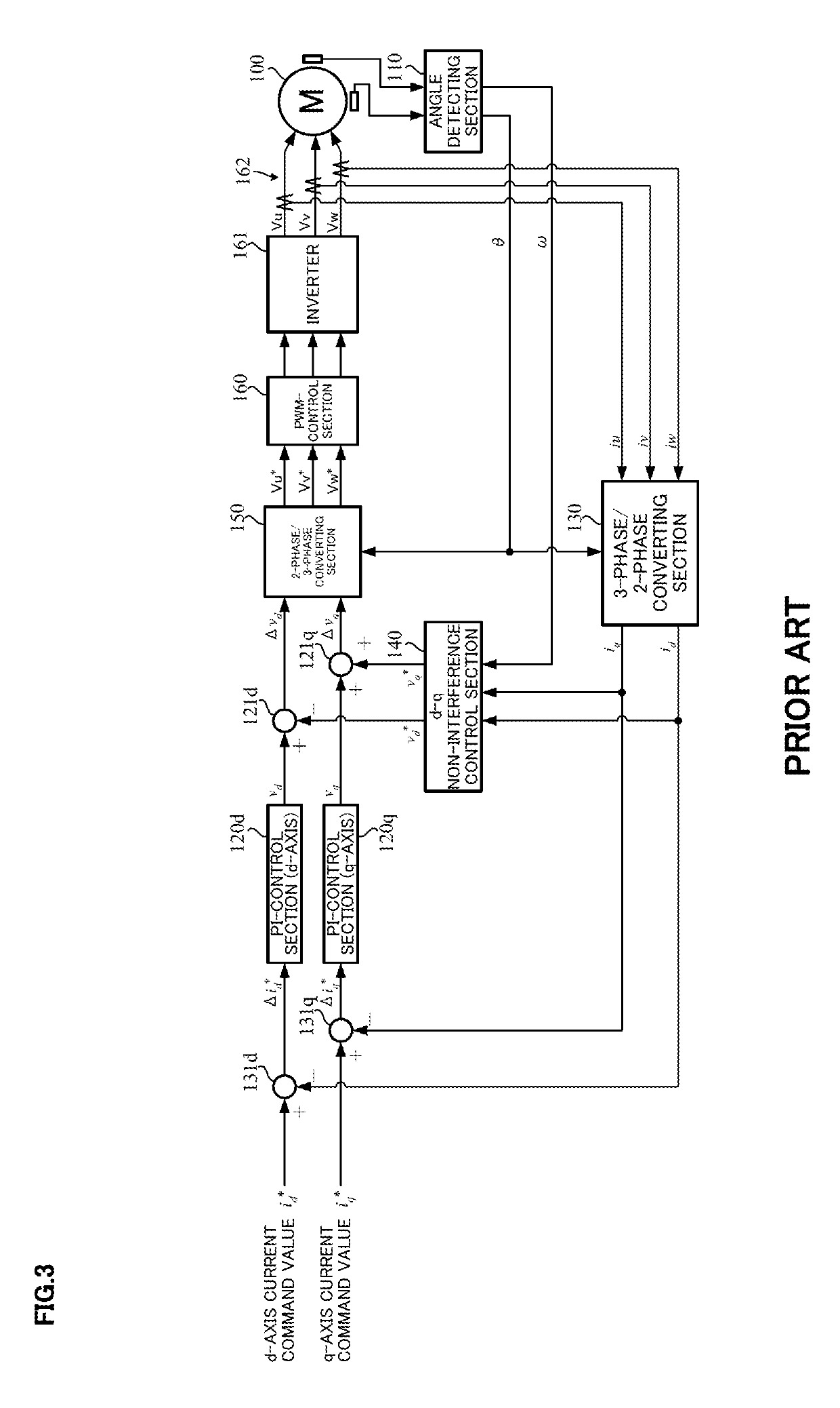
The electric power steering apparatus described in this patent uses a dq-axis disturbance observer to compensate for dead time in the inverter and motor back-EMF and interference voltage without adding other elements. This results in a smoother control, reduced sound and vibration, and reduced ripple in the motor. Additionally, the compensation is based on the voltage vector of spatial vector modulation, allowing for simultaneous compensation of dead time in multiple phases. Overall, this patent provides a more efficient and effective electric power steering system.

Problems solved by technology

As a result, a current waveform is distorted, and a responsibility of the current control and a steering feeling go down.
Since the back-EMF voltage of the motor in a while speed steering or a high speed steering, and the interference voltage between the windings operate as the disturbance against the current control, a steering follow-up performance and the steering feeling in turn-back steering are badly affected.
Since the dead time is nonlinear, the current waveform is distorted, the responsibility of the control is badly affected and the sound, the vibration and the torque ripple are generated.

Method used


Image

  • Electric power steering apparatus
  • Electric power steering apparatus
  • Electric power steering apparatus

Examples


Embodiment Construction

[0065]The present invention resolves a conventional problem by adapting a dq-axes disturbance observer of a vector control and a spatial vector modulation (a third harmonic superimposition, or the third harmonic superimposition and the dead time compensation). The precise dead time compensation in response to a switch timing of an inverter is realized by generating a dead time compensation value in accordance with a voltage vector of the spatial vector modulation. The dq-axes disturbance observer compensates a change of a current phase due to a back electromotive force (a back-EMF) of the motor and an interference voltage between windings in a while speed steering or a high speed steering and reduces a timing deviation of the dead time. As a result, the dead time compensation can be performed in the while speed steering or the high speed steering (particularly, in a region that a load is low and a modulation rate is low), and a current control response, a vibration and a ripple can ...


PUM


Abstract

[Problem]An object of the present invention is to provide an electric power steering apparatus of a vector control system that compensates a dead time of an inverter, a motor back-EMF and an interference voltage due to a mutual inductance between motor windings, improves a distortion of a current waveform and a responsibility of a current control, and suppresses a noise, vibration and a ripple.[Means for Solving the Problem]The present invention is the electric power steering apparatus that driving-controls a 3-phase brushless motor which applies an assist torque to a steering mechanism of a vehicle by using a current command value calculated based on at least a steering torque, and vector-controls the 3-phase brushless motor, via an inverter, by converting dq-axes command values converted from the current command value into 3-phase values, comprising a dq-axes disturbance observer to compensate respective axes disturbance voltages, which include a dead time of the inverter, for the dq-axes command values, or comprising: a dq-axes disturbance observer to compensate respective axes disturbance voltages, which include a dead time of the inverter, for the dq-axes command values and a spatial vector modulating section.

Description

CROSS REFERENCE TO RELATED APPLICATIONS[0001]This application is a National Stage of International Application No. PCT / JP2017 / 025916 filed Jul. 18, 2017, claiming priority based on Japanese Patent Application No. 2016-142622, filed Jul. 20, 2016 and Japanese Patent Application No. 2016-14262 filed Jul. 20, 2016.TECHNICAL FIELD[0002]The present invention relates to an electric power steering apparatus that enables to smoothly assist-control by vector-controlling a drive of a 3-phase brushless motor by using a dq-axes rotational coordinate system, and by compensating a disturbance such as a dead time of an inverter, aback electromotive force (a back-EMF) of the motor and an interference voltage due to a mutual inductance between windings, and in particular to the high-performance electric power steering apparatus that improves a distortion of a current waveform and a responsibility of a current control, and suppresses a noise, vibration, and a ripple by using a dq-axes disturbance obs...

Claims


Application Information

Patent Timeline
Patent Type & Authority Patents(United States)
IPC IPC(8): H02P21/00H02P27/08H02P21/14H02M7/5387B62D6/00H02P21/22B62D5/04H02P21/13H02M1/38H02M7/48H02P6/10H02P21/05
CPCB62D6/00H02P21/13B62D5/0463H02P27/08H02P21/14H02M7/53871H02M1/38H02M7/48B62D5/046H02P21/05H02P21/22H02P6/10H02M2001/385H02M1/385
Inventor MINAKI, RYOTAKASE, HIROAKISAWADA, HIDEKISUGAWARA, TAKAYOSHI
Owner NSK LTD
Learn More