
Zero echo time MR imaging

a mr imaging and zero echo technology, applied in the field of magnetic resonance (mr) imaging, can solve the problem that the k-space data is slightly incomplete in the k-space center

Active Publication Date: 2019-07-23
KONINKLJIJKE PHILIPS NV
View PDF2 Cites 0 Cited by
  • Summary
  • Abstract
  • Description
  • Claims
  • Application Information

AI Technical Summary

Benefits of technology

The invention helps to get accurate signals from the center of k-space in a ZTE acquisition scheme, which improves image quality. It also helps measure the variation in the receiver's gain during the dead time, which can be used to compensate for the dead time effects in the signals acquired at non-zero readout strengths.

Problems solved by technology

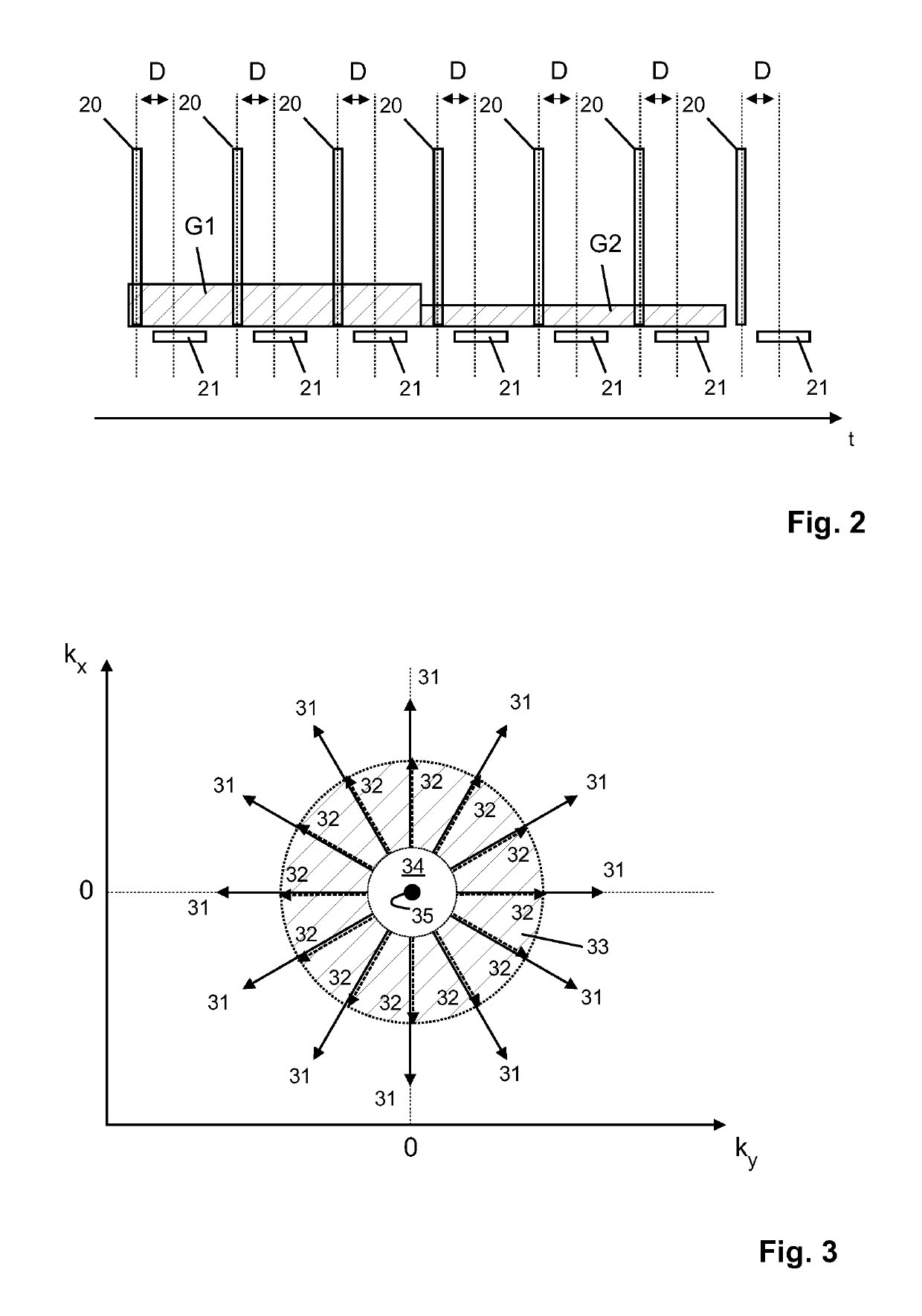
A challenge in ZTE imaging is that the k-space data are slightly incomplete in the k-space center due to the initial dead time that is caused by the finite duration of the RF pulse, transmit-receive switching, and signal filtering.

Method used


Image

  • Zero echo time MR imaging
  • Zero echo time MR imaging

Examples


Embodiment Construction

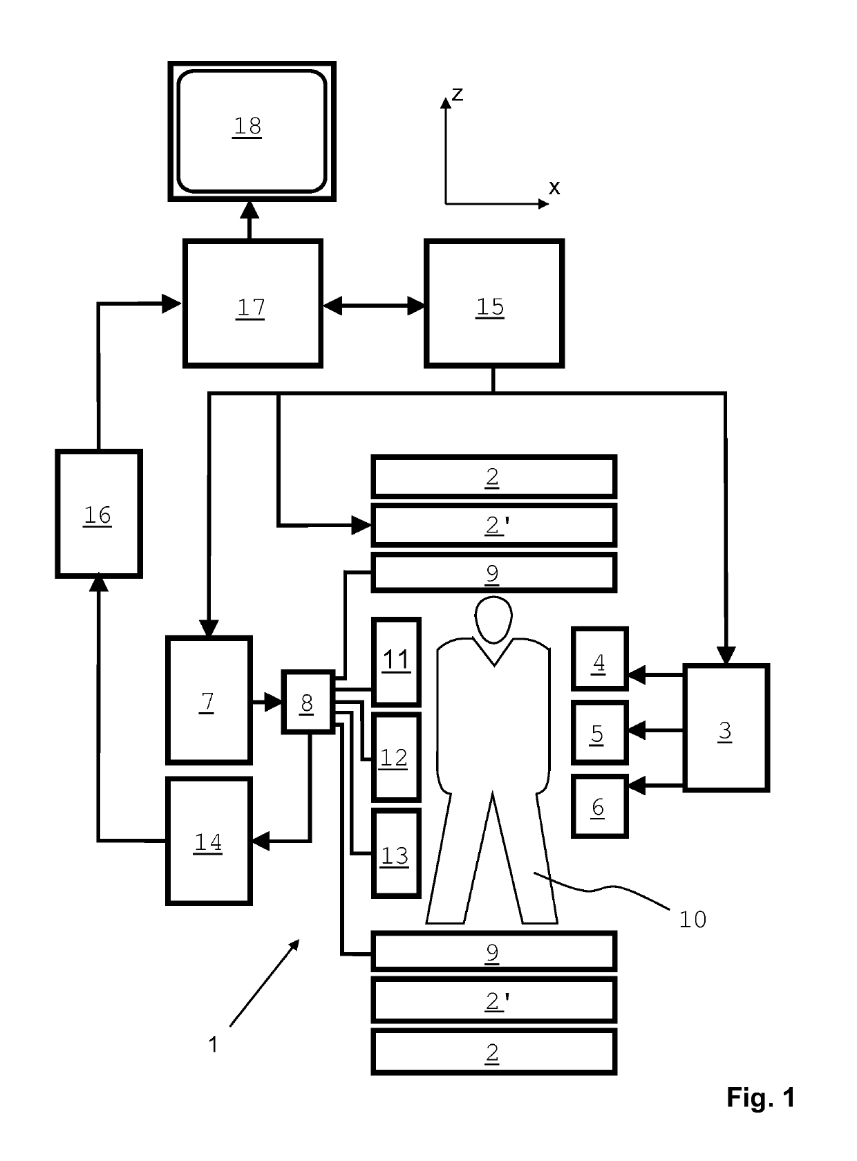
[0031]With reference to FIG. 1, a MR device 1 which can be used for carrying out the method of the invention is shown. The device comprises superconducting or resistive main magnet coils 2 such that a substantially uniform, temporally constant main magnetic field B0 is created along a z-axis through an examination volume. The device further comprises a set of (1st, 2nd, and—where applicable—3rd order) shimming coils 2′, wherein the current flow through the individual shimming coils of the set 2′ is controllable for the purpose of minimizing B0 deviations within the examination volume.

[0032]A magnetic resonance generation and manipulation system applies a series of RF pulses and switched magnetic field gradients to invert or excite nuclear magnetic spins, induce magnetic resonance, refocus magnetic resonance, manipulate magnetic resonance, spatially and otherwise encode the magnetic resonance, saturate spins, and the like to perform MR imaging.

[0033]More specifically, a gradient puls...


PUM


Abstract

The invention relates to a method of MR imaging of an object positioned in an examination volume of a MR device (1). It is an object of the invention to enable ‘silent’ ZTE imaging with improved sampling of k-space center. According to the invention, the object (10) is subjected to an imaging sequence of RF pulses (20) and switched magnetic field gradients, which imaging sequence is a zero echo time sequence comprising: i) setting a readout magnetic field gradient having a readout direction and a readout strength (G1, G2); ii) radiating a RF pulse (20) in the presence of the readout magnetic field gradient; iii) acquiring a FID signal in the presence of the readout magnetic field gradient, wherein the FID signal represents a radial k-space sample (31, 32), wherein the acquisition of the FID signal is started at an acquisition time at which a receiver gain of the MR device (1) has not yet stabilized after the radiation of the RF pulse (20); iv) incrementally varying the readout direction; v) sampling a spherical volume in k-space by repeating steps i) through iv) a number of times. Finally, a MR image is reconstructed from the acquired FID signals. Moreover, the invention relates to a MR device and to a computer program for a MR device.

Description

CROSS REFERENCE TO RELATED APPLICATIONS[0001]This application is a U.S. national phase application of International Application No. PCT / EP2015 / 070519, filed on Sep. 8, 2015, which claims the benefit of EP Application Serial No. 14184590.9 filed on Sep. 12, 2014 and are incorporated herein by reference.FIELD OF THE INVENTION[0002]The invention relates to the field of magnetic resonance (MR) imaging. It concerns a method of MR imaging. The invention also relates to a MR device and to a computer program to be run on a MR device.BACKGROUND OF THE INVENTION[0003]Image-forming MR methods which utilize the interaction between magnetic fields and nuclear spins in order to form two-dimensional or three-dimensional images are widely used nowadays, notably in the field of medical diagnostics, because for the imaging of soft tissue they are superior to other imaging methods in many respects, do not require ionizing radiation and are usually not invasive.[0004]According to the MR method in gener...

Claims


Application Information

Patent Timeline
Patent Type & Authority Patents(United States)
IPC IPC(8): G01R33/48G01R33/565G01R33/56
CPCG01R33/4816G01R33/565G01R33/56G01R33/4826G01R33/48
Inventor SMINK, JOUKEGROEN, JOHANNES PETRUS
Owner KONINKLJIJKE PHILIPS NV
Learn More