Droplet ejecting device

a technology of ejection device and droplet, which is applied in the field of droplet ejection device, can solve the problems of insufficient cancelling capacity of fixed reference capacitor and inability to suppress actuation pulses by subtraction, and achieve the effect of accurate analysis of ejection unit status, easy to transcend detection signals, and insufficient capacitance of electromechanical transducers

Active Publication Date: 2020-01-14
CANON PRODN PRINTING NETHERLANDS BV
View PDF10 Cites 0 Cited by
  • Summary
  • Abstract
  • Description
  • Claims
  • Application Information

AI Technical Summary

Benefits of technology

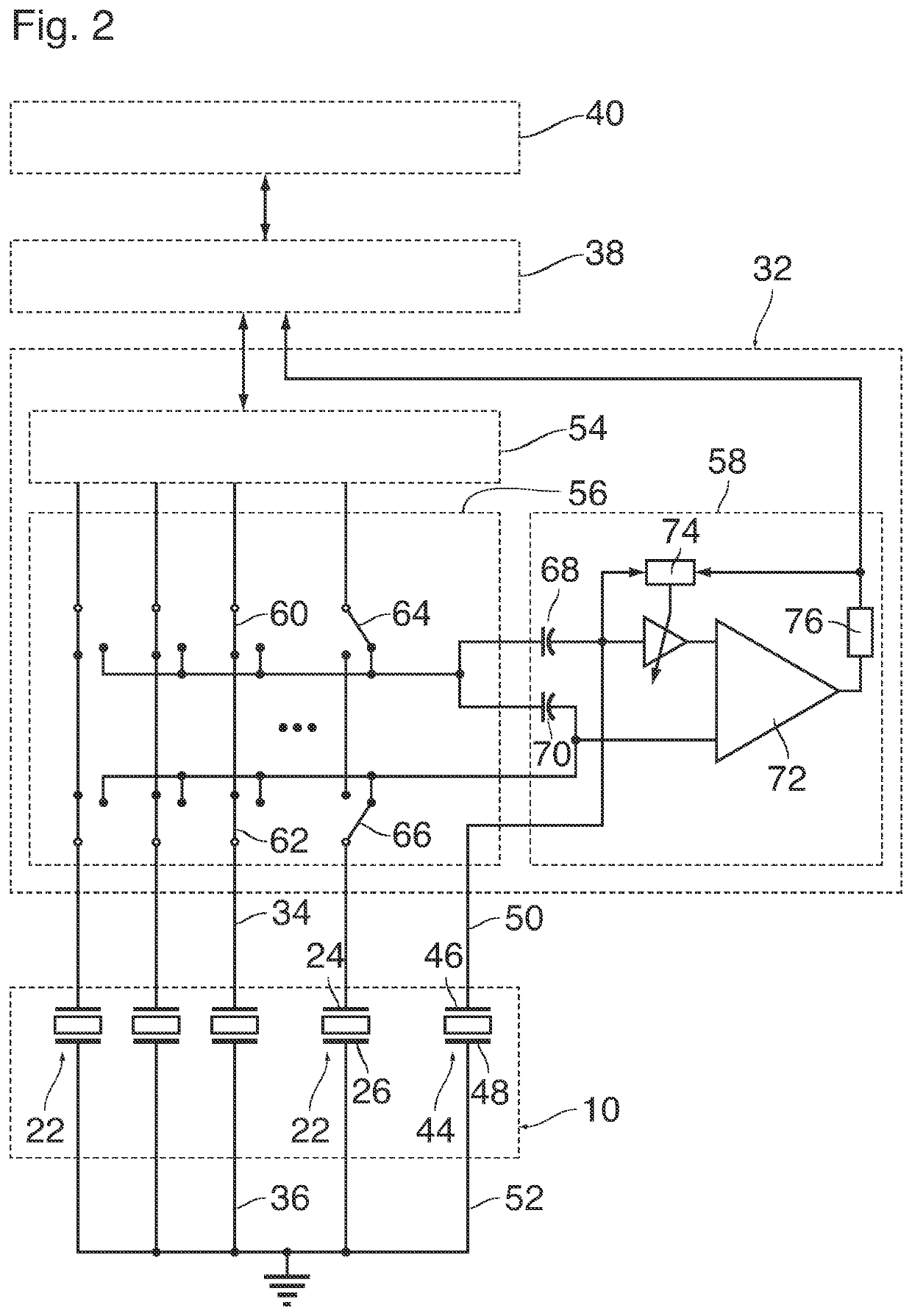
[0007]The invention has the advantage that even during application of an actuation pulse, a measurement of the pressure fluctuations may take place, since the actuation pulses in the detection signal of the at least one of the ejection units and the reference unit cancel by the subtraction in the control circuit. Only the detection signal of the at least one of the ejection units comprises a contribution from the pressure fluctuations, since, in operation, the reference duct of the reference unit does not contain liquid. Therefore, the signal caused by the pressure fluctuations is not lost by the subtraction.
[0008]Based on the resulting signal, only containing signal contributions from the pressure fluctuations, an accurate analysis of the ejection unit status is enabled. Moreover, in view of the removal of the actuation signal by subtraction, it is enabled to analyze the pressure fluctuations in the liquid during the application of the actuation pulse.
[0009]The inventors have found that a fixed reference capacitor is insufficient for cancelling an actuation pulse, because the capacitance of an electromechanical transducer is not sufficiently stable. As a result, the actuation pulse may not be sufficiently suppressed by subtraction. Since the actuation pulse is so much larger than the detection signal, a small remaining part of the actuation pulse will easily transcend the detection signal. Further, the availability of a reference transducer with a reference duct without liquid makes the detection of the signals from the transducers of the ejection units more robust against vibrations that may be induced in the nozzle head from outside, against a temperature drift of the electronic properties of the transducers, and against ageing effects of the transducers. Such effects, which may compromise the detection of the signals that shall be processed for monitoring the functioning of the ejection units, will affect the transducers of the ejection units and the reference transducer essentially in the same manner, so that, by subtracting the signals of these transducers from one another, it is possible to suppress the disturbing effects.
[0013]In conventional droplet ejection devices of this type, is it common practise that a detection signal of a transducer of an ejection unit is received only during intervals between the actuation pulses for that transducer. That is, the transducer is either connected to a signal source of the control circuit so that a control signal may be applied, or it is disconnected from this signal source and connected instead to a detection circuit. The reason is that the actuation pulse for the transducer would normally have such a high amplitude that it would mask the detection signal. In the device according to the invention, however, the same actuation pulses are applied to the transducer of the ejection unit that is to be monitored and to the reference transducer, and these pulses will cancel each other in the comparison or bridge circuit, so that what is detected is only the difference between the two detection signals, this difference being indicative of pressure waves that are present only in the liquid in the ejection unit but not in the dummy duct. In this way, it is possible to obtain a detection signal even in the periods in which the transducer is active, which permits to monitor the function of ejection unit more closely.

Problems solved by technology

The inventors have found that a fixed reference capacitor is insufficient for cancelling an actuation pulse, because the capacitance of an electromechanical transducer is not sufficiently stable.
As a result, the actuation pulse may not be sufficiently suppressed by subtraction.

Method used


Image

  • Droplet ejecting device
  • Droplet ejecting device

Examples


Embodiment Construction

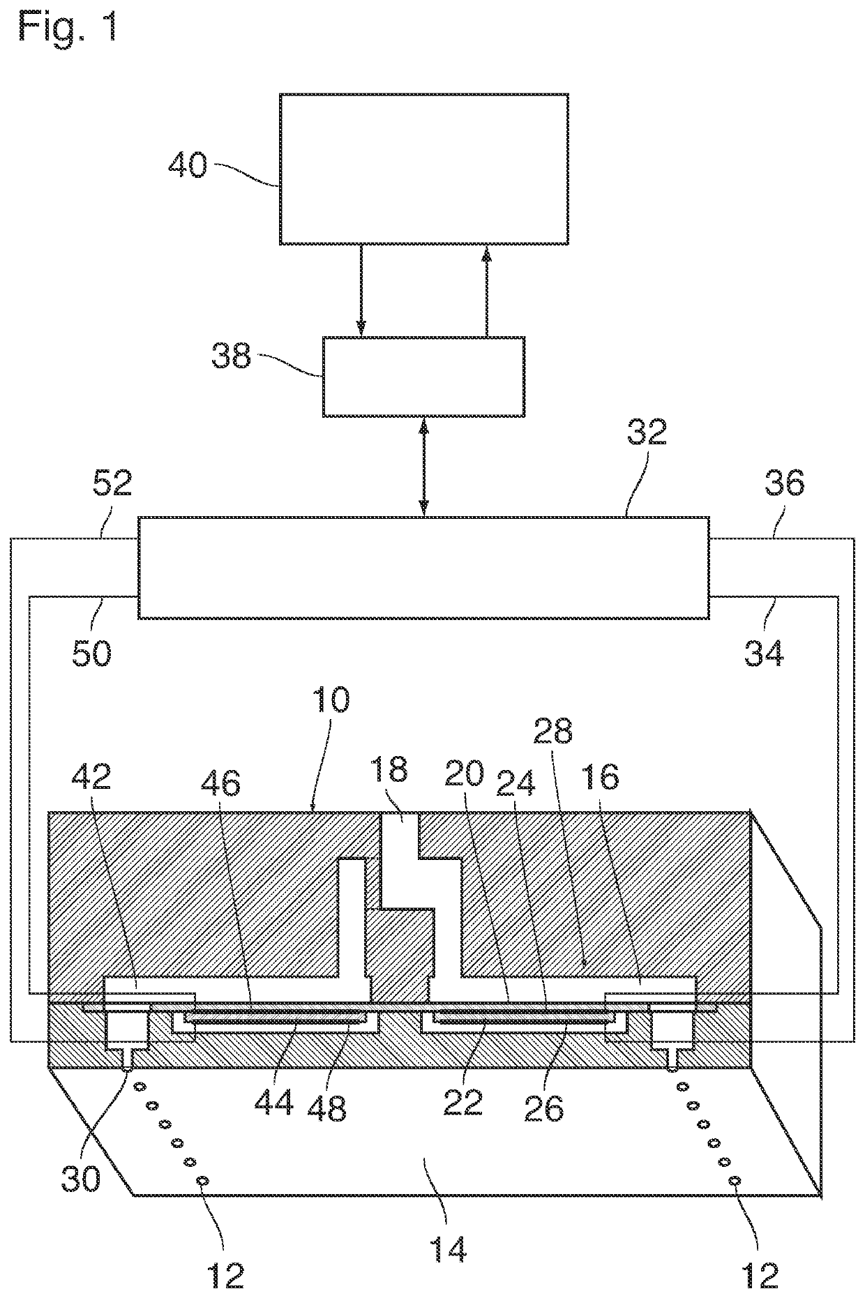
[0018]As is shown in FIG. 1, a droplet ejection device which may for example form part of an ink jet printer comprises a nozzle head 10 with plurality of nozzles 12 formed in a flat nozzle face 14. The nozzle head 10 may for example be formed by MEMS technology (Micro Electro Mechanical System).

[0019]Each nozzle 12 is connected to one end of a duct 16 that is filled with liquid ink. An opposite end of the duct 16 is connected to an ink supply line 18 that is common to all the nozzles 12 and ducts 16 of the entire nozzle head. One wall of each duct 16 is formed by a flexible membrane 20 to which an electromechanical transducer 22 is attached on the side outside of the duct 16. The transducer 22 has a number of electrodes 24 only two of which have been shown here. The transducer 22 may be a piezoelectric transducer with a plurality of layers of piezoelectric material stacked one upon the other and with internal electrodes intervening therebetween. The internal electrodes inside the pi...


PUM


Abstract

A droplet ejection device has a nozzle head with a plurality of ejection units, each of which includes a nozzle, a duct connected to the nozzle, and an electromechanical transducer arranged to create a pressure wave in a liquid in the duct so as to expel a droplet of the liquid from the nozzle. The device further includes an electronic control circuit arranged to apply control signals to the transducers and to receive detection signals that are generated in the transducers in response to the transducer being exposed to pressure fluctuations. The nozzle head includes a reference duct which has an electromechanical transducer serving as a reference transducer. The control circuit is arranged to subtract a detection signal of the reference transducer from a detection signal of at least one of the ejection units.

Description

CROSS REFERENCE TO RELATED APPLICATIONS[0001]This application is a Continuation of PCT International Application No. PCT / EP2016 / 069223 filed on Aug. 12, 2016, which claims priority under 35 U.S.C.§ 119(a) to Patent Application No. 15182253.3 filed in Europe on Aug. 25, 2015, all of which are hereby expressly incorporated by reference into the present application.BACKGROUND OF THE INVENTION[0002]The invention relates to a droplet ejection device having a nozzle head with a plurality of ejection units each of which comprises a nozzle, a duct connected to the nozzle, and an electromechanical transducer arranged to create a pressure wave in a liquid in the duct so as to expel a droplet of the liquid from the nozzle, the device further comprising an electronic control circuit arranged to apply control signals to the transducers and to receive detection signals that are generated in the transducers in response to the transducer being exposed to pressure fluctuations in the liquid.[0003]Su...

Claims


Application Information

Patent Timeline
Patent Type & Authority Patents(United States)
IPC IPC(8): B41J2/045B41J2/14
CPCB41J2/0451B41J2/14032B41J2/0453B41J2/04581B41J2/14233B41J2002/14354
Inventor KHALATE, AMOL A.SIMONS, JOHANNES M. MMIHAILOVIC, MARKO
Owner CANON PRODN PRINTING NETHERLANDS BV
Why Eureka
Try Eureka