Video display apparatus and control method of video display apparatus
a video display and control method technology, applied in the field of video display apparatus and control method of video display apparatus, can solve the problems of difficult intuitive grasping of the direction in which the cut position moves on the fish, and the position relationship between the fish-eye video and the cut video is difficult to grasp, so as to achieve the effect of easy grasping the movement of the cut position
- Summary
- Abstract
- Description
- Claims
- Application Information
AI Technical Summary
Benefits of technology
Problems solved by technology
Method used
Image

Examples
first embodiment
[0027](First Embodiment)
[0028]
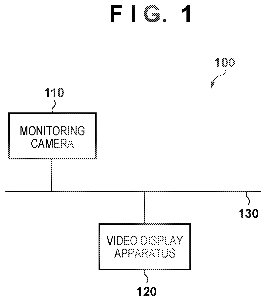
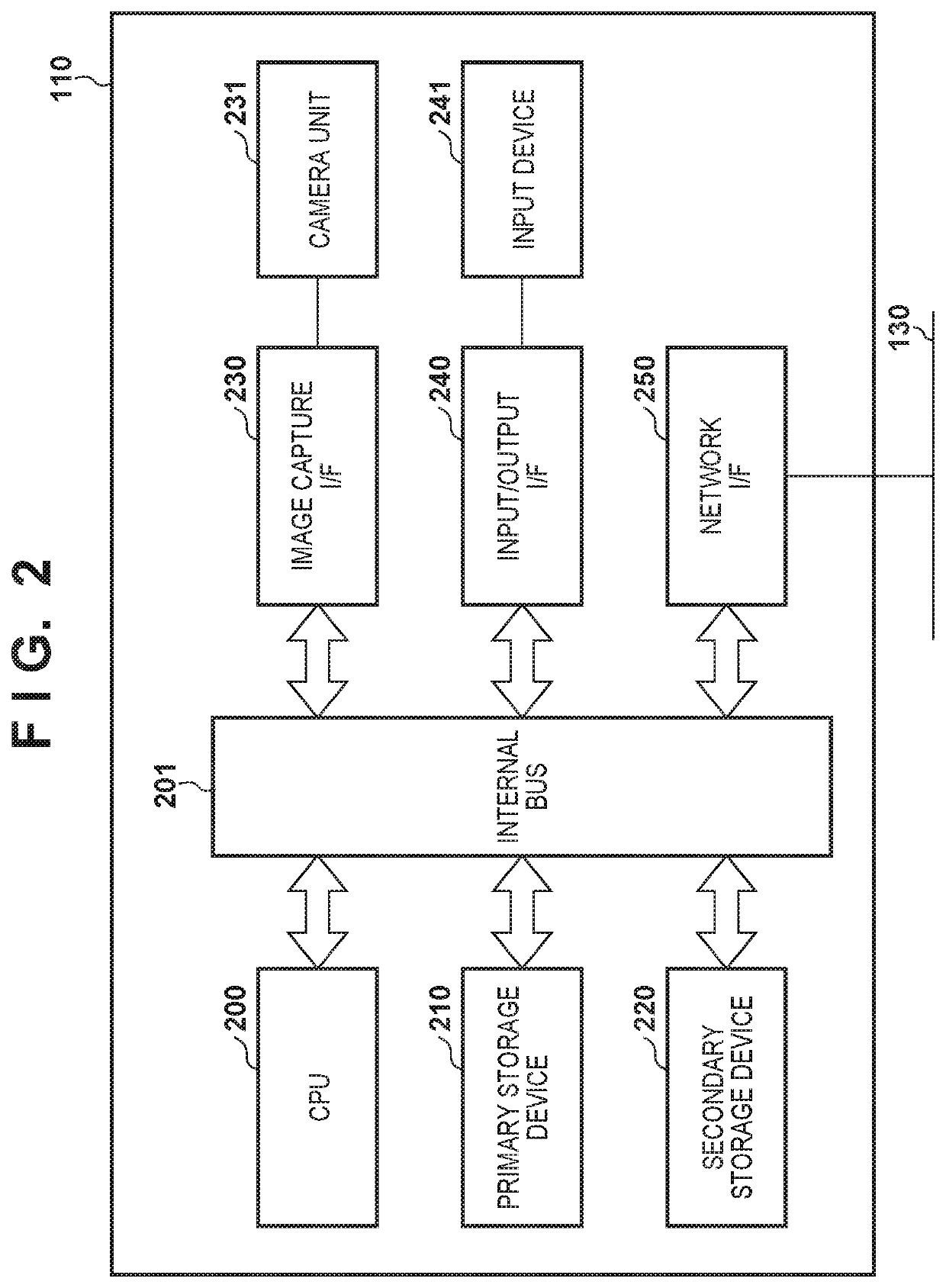
[0029]In this embodiment, an example in which an image (display form) representing the moving direction of a cut position on an omnidirectional video is switched based on installation data (ceiling mount, desk mount, wall mount, and the like) representing the installation condition of a camera and superimposed on the omnidirectional video will be described. Note that although an omnidirectional video that is a video captured via a fish-eye lens will be exemplified, this embodiment is applicable to another video as well. For example, this embodiment is applicable to a video captured via a normal lens. In addition, this embodiment is applicable to a panoramic image that is an image formed by connecting a plurality of videos.
[0030]More specifically, if the installation condition is ceiling mount or desk mount, as an image (display form) in a case in which the cut position of a cut video obtained by cutting a part of an omnidirectional video is moved by a p...
second embodiment
[0093](Second Embodiment)
[0094]
[0095]In the first embodiment, an example in which the display form (auxiliary line) representing the moving direction on the omnidirectional video is switched in accordance with the installation condition has been described. When this is executed, the user can execute intuitive pan / tilt control without being conscious of the installation condition. However, if a wrong installation condition is set, the user may be unable to know that the moving direction of pan / tilt on the omnidirectional video changes in accordance with the installation condition. As a solution to this, in this embodiment, an example in which when an installation condition is set, the user is notified that the moving direction of pan / tilt changes in accordance with the installation condition will be described.
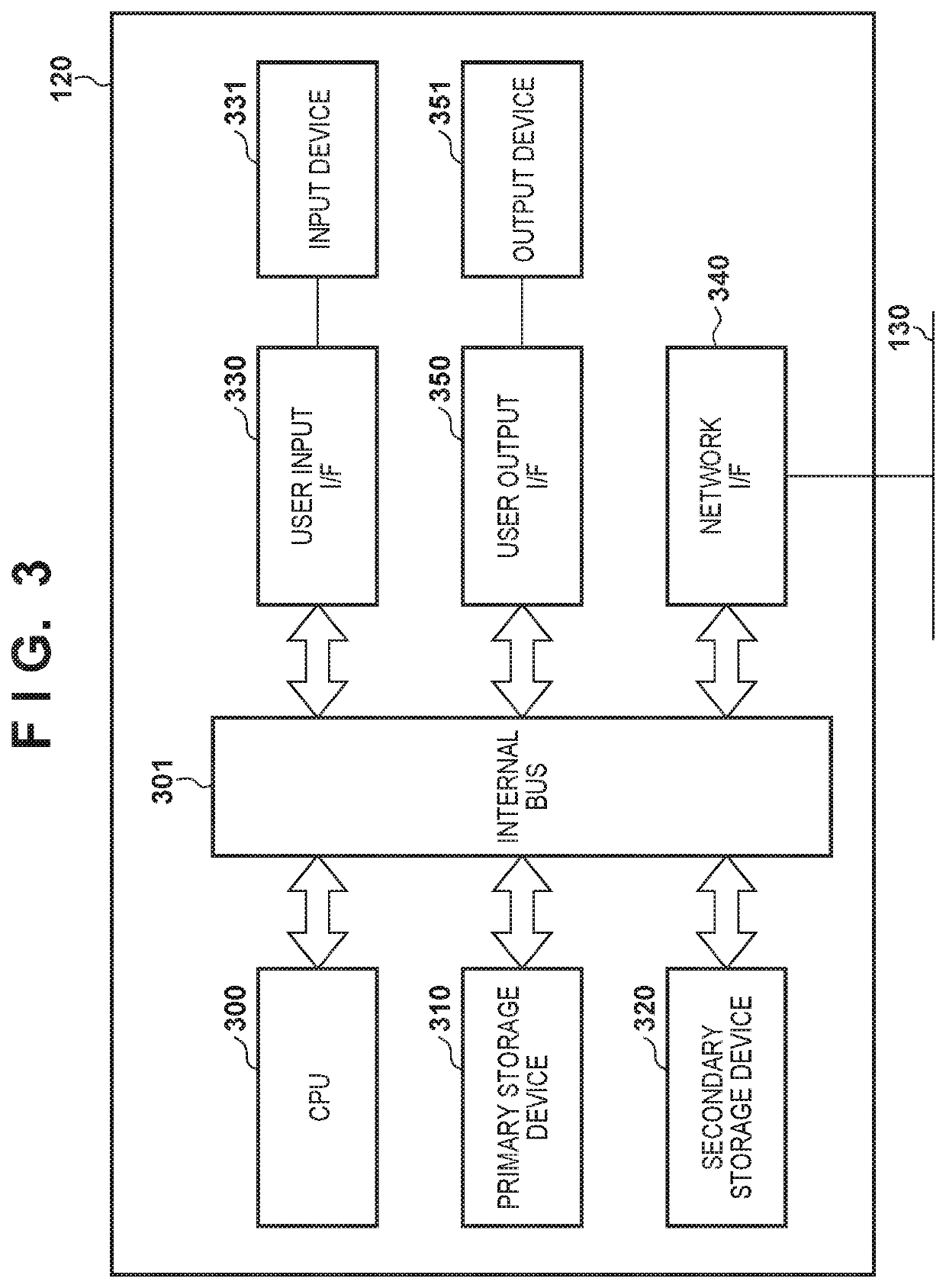
[0096]For example, the user inputs an installation condition via an input device 331 represented by a mouse or the like of a video display apparatus 120. Upon accepting the inpu...
third embodiment
[0104
[0105]
[0106]In the second embodiment, an example in which when an installation condition is set, the user is notified that the moving direction of pan / tilt changes in accordance with the installation condition has been described. In the third embodiment, an example in which the user is notified of the enabled / disabled state of auto-flip in accordance with the installation condition will be described.
[0107]
[0108]FIG. 11 is a flowchart showing an example of the processing procedure of a video display apparatus 120 when installation data is input. In step S1101, the video display apparatus 120 determines whether installation data is set. If installation data is set, the process advances to step S1102. On the other hand, if installation data is not set, the processing ends. In step S1102, the video display apparatus 120 determines whether the installation data corresponds to ceiling mount. If the installation data corresponds to ceiling mount, the process advances to step S1103. On...
PUM
 Abstract
Description
Claims
Application Information
PatSnap Eureka turns technology decisions into work you can execute. Powered by our Innovation Knowledge Graph, it runs expert workflows across engineering, life sciences, materials and intellectual property. Get your review-ready output in minutes.


