
Buildup device

a technology of buildup device and buildup shaft, which is applied in the direction of metal-working feeding device, magnetic core manufacturing, manufacturing tools, etc., can solve the problems of high speed inability to efficiently reduce the load caused by frictional resistance, and the motor and other components can be affected by vibration operation at high speed. , to achieve the effect of preventing breakage and failure, reducing vibration, and reducing costs

Active Publication Date: 2020-01-21
SANKYO SEISAKUSHO
View PDF10 Cites 0 Cited by
  • Summary
  • Abstract
  • Description
  • Claims
  • Application Information

AI Technical Summary

Benefits of technology

The present invention is a device for reducing vibration from a press machine to prevent breakage and failure of the motor. It improves the life of the motor and the entire buildup device, reducing costs at the production site. The device also builds up plate-shaped cores with high accuracy by reducing vibration from the press machine. The motor is stabilized, preventing its motion from being affected by the vibration from the press machine, and the rotary force of the motor is utilized for efficient operation of the device. The buildup device is suitable for manufacturing cores by building them after rotating each of the cores.

Problems solved by technology

However, if operation at high speed is attempted in a conventional typical buildup device by increasing rotation speed of a rotary drive device, a load is applied to a motor and other components, and thus the load may cause breakage or failure in the motor or the like.
However, in the buildup device of JP-A-2013-116497 in which compressed air is supplied to allow the die holder to smoothly rotate during building up a core after rotating the core so that frictional resistance in the rotating and sliding portion is reduced to reduce a load, there is a problem in which a load caused by the frictional resistance can be reduced, but a load applied to a motor and other components caused by vibration in operation at high speed cannot be efficiently reduced.
In this way, the conventional buildup device has a problem in which if a rotary drive unit is attempted to be rotated at high speed, a load caused by vibration increases, and if the load caused by vibration is attempted to be reduced, rotation speed of the rotary drive unit needs to be reduced.

Method used


Image

  • Buildup device
  • Buildup device
  • Buildup device

Examples


Embodiment Construction

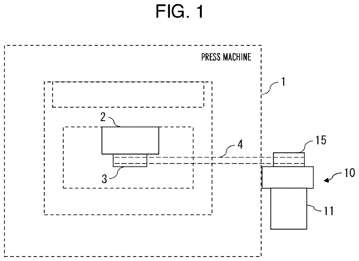
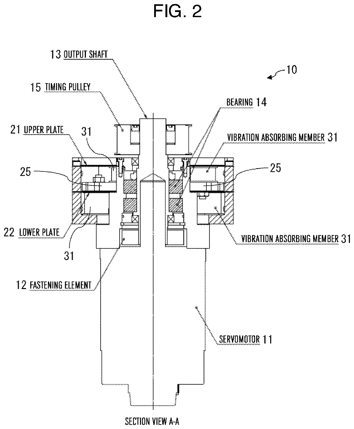
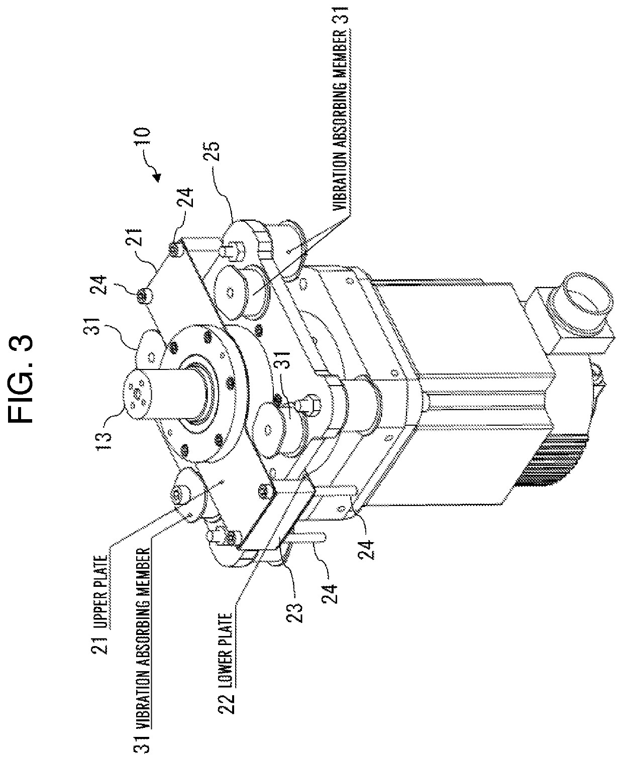
[0026]FIG. 1 is a schematic diagram of a press machine to which a buildup device in accordance with the present invention is attached. A buildup device 10 in accordance with the present invention can be attached to a press machine 1 that stamps out a plate-shaped core of a steel plate or the like, and is used to build up the plate-shaped core stamped out by the press machine 1 after rotating the core. Thickness of the plate-shaped core stamped out is not uniform, and thus building up a plurality of plate-shaped cores causes an upper surface of the built-up cores to incline. To prevent this inclination of the built-up cores, the plate-shaped core stamped out is built up after rotated by a predetermined angle. The buildup device 10 in accordance with the present invention transfers power to a buildup mold 2 attached to the press machine to rotate the plate-shaped core by the predetermined angle. When the press machine 1 stamps out the plate-shaped core, vibration occurs. The buildup d...


PUM

PropertyMeasurementUnit
degree of freedomaaaaaaaaaa
angleaaaaaaaaaa
degree of freedomaaaaaaaaaa

Abstract

There is provided a buildup device that builds up a plate-shaped core after rotating the core by a predetermined angle, and that includes a servomotor, a damping plate attached to the servomotor, at least one upper plate provided above the damping plate, at least one lower plate provided below the damping plate, and a plurality of vibration absorbing members attached to the damping plate. The upper plate and the lower plate restrict a degree of freedom of vibration to one direction, and the vibration absorbing members absorb vertical vibration.

Description

CROSS-REFERENCE TO RELATED APPLICATION[0001]This application is based upon and claims the benefit of priority from Japanese Patent Application No. 2015-139887, filed Jul. 13, 2015, the entire contents of which are incorporated herein by reference.BACKGROUND OF THE INVENTION[0002]The present invention relates to a buildup device that builds up plate-shaped cores stamped out after rotating each of the cores.[0003]In recent years, increase in demand for mass production of built-up cores has required a buildup device capable of building up cores at high speed when built-up cores are produced by building up plate-shaped cores to increase production efficiency. To achieve the buildup device capable of building up cores at high speed, JP-A-2011-62732 discloses a structure as follows: a side face of a built-up iron core is supported by an inner wall surface of a lower mold; a surface of a lowermost core of the built-up iron core is supported by a back pressure device; the inner wall surface...

Claims


Application Information

Patent Timeline
Patent Type & Authority Patents(United States)
IPC IPC(8): H02K5/24B21D22/08
CPCH02K5/24B21D22/08B21D28/02B21D43/22H02K15/02B21D28/14B30B15/0076H01F3/02H01F41/0206H01F41/0233
Inventor SUZUKI, KENGO
Owner SANKYO SEISAKUSHO
Learn More