
Apparatus and method for determining key performance indicators

a technology of performance indicators and applicators, applied in the field of determining key performance indicators, can solve the problems of significant slowing down of analysis process, time-consuming and laborious to analyze huge amounts of data, and large amounts of data that needs to be considered, so as to achieve quick and efficient results

Active Publication Date: 2020-01-21
GENERAL ELECTRIC CO
View PDF7 Cites 0 Cited by
  • Summary
  • Abstract
  • Description
  • Claims
  • Application Information

AI Technical Summary

Benefits of technology

[0009]The present invention is directed to providing data optimizations and visualizations across an enterprise of plants located (potentially) across the globe. More specifically, key performance indicators may be quickly and efficiently obtained across an entire enterprise of plants, machines, or manufacturing lines. In some embodiments, the invention described herein may be implemented at the cloud and may be applied on a global basis across numerous plants, locations, and / or industrial machines separated by great distances. One feature of this invention is the ability to perform time window data slicing of vast amounts of data sets over multiple processors that are operating simultaneously and in parallel. This enables a vast amount of data to be analyzed and results returned for consideration in an acceptable amount of time. The invention herein may optionally be implemented using a computerized industrial internet of things analytics platform that may be deployed at the cloud.

Problems solved by technology

Unfortunately, there are huge amounts of data that needs to be considered.
Analyzing huge amounts of data takes time, and in current systems processing large amounts of data significantly slows the analysis process.
Previous attempts to address these problems have been made, but unfortunately, have not been successful.

Method used


Image

  • Apparatus and method for determining key performance indicators
  • Apparatus and method for determining key performance indicators
  • Apparatus and method for determining key performance indicators

Examples


Embodiment Construction

[0025]The present approaches advantageously obtain key performance indicator information quickly and efficiently across an entire enterprise of plants (or across multiple machines). The approaches described herein may be implemented at the cloud (e.g., by the Predix™ platform available from General Electric Company) and may be applied on a global basis across numerous plants, locations, and / or industrial machines located at great distances such as worldwide.

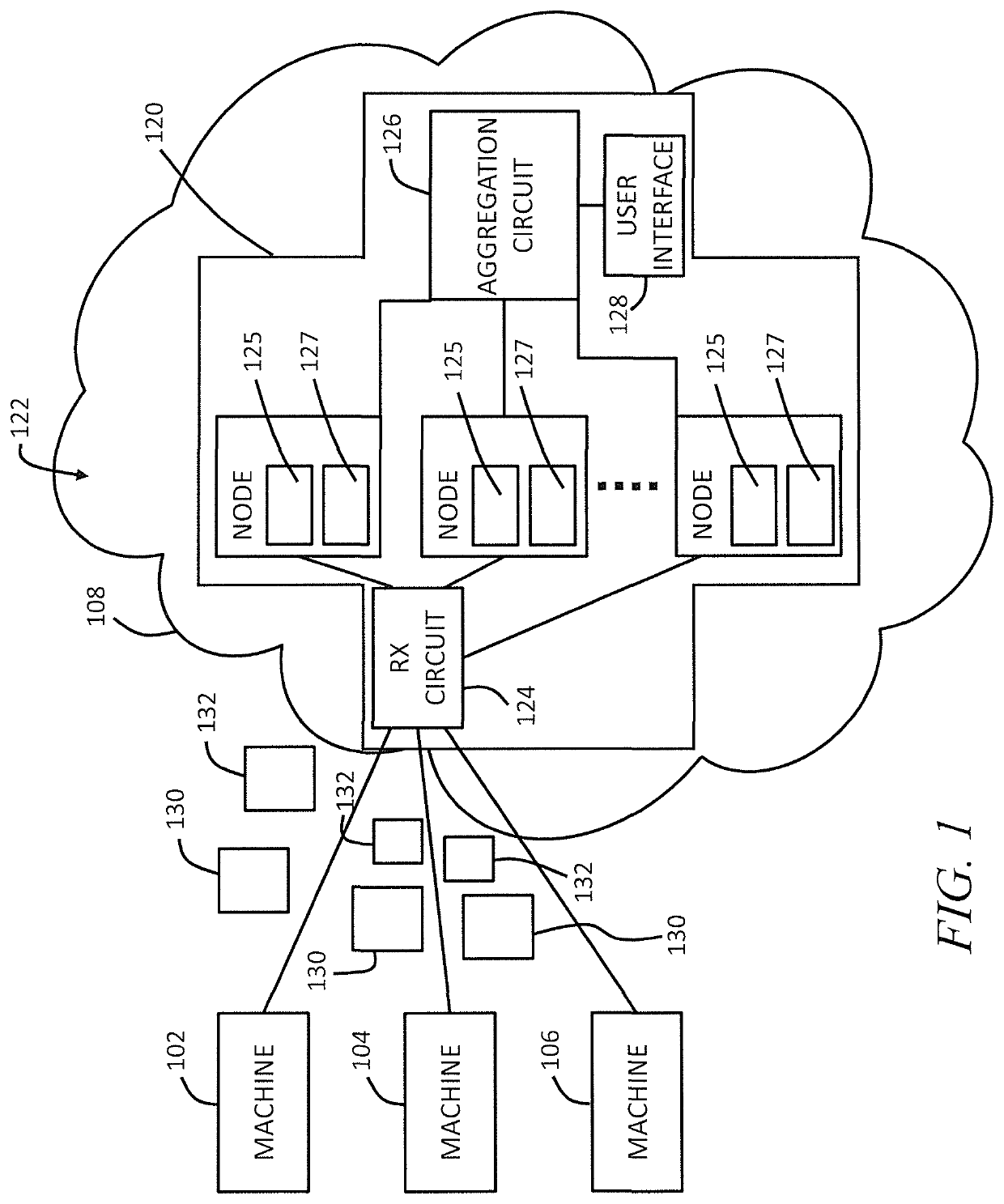
[0026]Referring now to FIG. 1, one example of a system that processes downtime records in parallel includes machines 102, 104, and 106, and a cloud 108. Within the cloud 108 is a data center 120. The data center 120 includes a plurality of nodes 122, a receiver circuit 124, an aggregation circuit 126, and a user interface 128.

[0027]Machines 102, 104, and 106 may be located at a single manufacturing site, factory, or plant. Although many of the examples described herein show the machines as being at a single plant, it will be appr...


PUM


Abstract

A data processing apparatus is deployed at a cloud network, and includes a plurality of data nodes, a receiver circuit, and an aggregation circuit. The receiver circuit is coupled to the plurality of data nodes and is configured to receive downtime records from a plurality of industrial machines, and to selectively route the downtime records to selected ones of the plurality of data nodes based upon a predetermined criteria. Each of the plurality of data nodes comprises a control circuit and a memory. Each control circuit is configured to, in parallel with the other control circuits, to further populate the downtime records with other data related to the operation of the machines, determine one or more time windows for each of the records, and divide the records according to the time windows.

Description

BACKGROUND OF THE INVENTIONField of the Invention[0001]The subject matter disclosed herein generally relates to determining key performance indicators for machines, groups of machines, or manufacturing lines.Brief Description of the Related Art[0002]Various types of industrial machines are used to perform various manufacturing operations and tasks. For instance, some machines are used to create and finish parts associated with wind turbines. Other machines are used to create mechanical parts or components utilized by vehicles. Still other machines are used to produce electrical parts (e.g., resistors, capacitors, and inductors to mention a few examples). Industrial machines often operate together in plants or factories.[0003]High volume, highly automated manufacturing processes or lines also exist. For instance, processes exist to manufacture paper towels, diapers, or bottling soda to mention a few examples. The machines used in these processes do not stand alone, but are part of th...

Claims


Application Information

Patent Timeline
Patent Type & Authority Patents(United States)
IPC IPC(8): H04L12/26G06F16/2458H04L29/08
CPCG06F16/2471H04L43/0805H04L67/10G05B19/4183G05B23/0272G05B2219/31288G06F16/11H04L67/12Y02P90/02G05B19/4185
Inventor SAGE, PETERRAISARDAR, ASHISH
Owner GENERAL ELECTRIC CO
Learn More