Aircraft lighting system

a technology for aircraft and lighting, applied in the field of aircraft and lighting systems, can solve the problems of increased pollution attributable, additional type of pollution such as sight pollution, and the unfavorable view of aircraft by people on the ground, and achieve the effect of reducing the visibility of aircraft in the sky

Active Publication Date: 2020-01-28
THE BOEING CO
View PDF1 Cites 5 Cited by
  • Summary
  • Abstract
  • Description
  • Claims
  • Application Information

AI Technical Summary

Benefits of technology

[0008]An embodiment of the present disclosure provides an aircraft lighting system comprising a set of lamps visible on an exterior of an aircraft and a controller in the aircraft. The controller activates the set of lamps to emit light and modulates an intensity of the light from the set of lamps at a set of frequencies that is detectable by a remote collision avoidance system in a remote aircraft during flight. The light from the set of lamps at the set of frequencies is perceived as continuous by a person looking at the aircraft in a sky, reducing visibility of the aircraft in the sky.
[0010]Yet another embodiment of the present disclosure provides a method for automating detection and avoidance for an aircraft. The process activates a set of lamps visible on an exterior of an aircraft to emit light. The process modulates an intensity of light from the set of lamps at a set of frequencies that is detectable by a remote collision avoidance system in a remote aircraft during flight. The light from the set of lamps at the set of frequencies is perceived as continuous by a person looking at the aircraft in a sky, reducing visibility of the aircraft in the sky.

Problems solved by technology

Aircraft engines emit air pollution in the form of heat, noise, particulates, and gases which can affect the environment.
Even with reductions in emissions from automobiles and more efficient aircraft, the rapid growth of air travel has contributed to an increase in pollution that is attributable to the air travel.
These and other types of uses of aircraft increase visual clutter, which causes an additional type of pollution such as sight pollution.
Sight pollution is the undesired view of aircraft by persons on the ground.
For example, having hundreds of aircraft cluttering a scenic view increases the sight pollution for people.

Method used


Image

  • Aircraft lighting system
  • Aircraft lighting system
  • Aircraft lighting system

Examples


Embodiment Construction

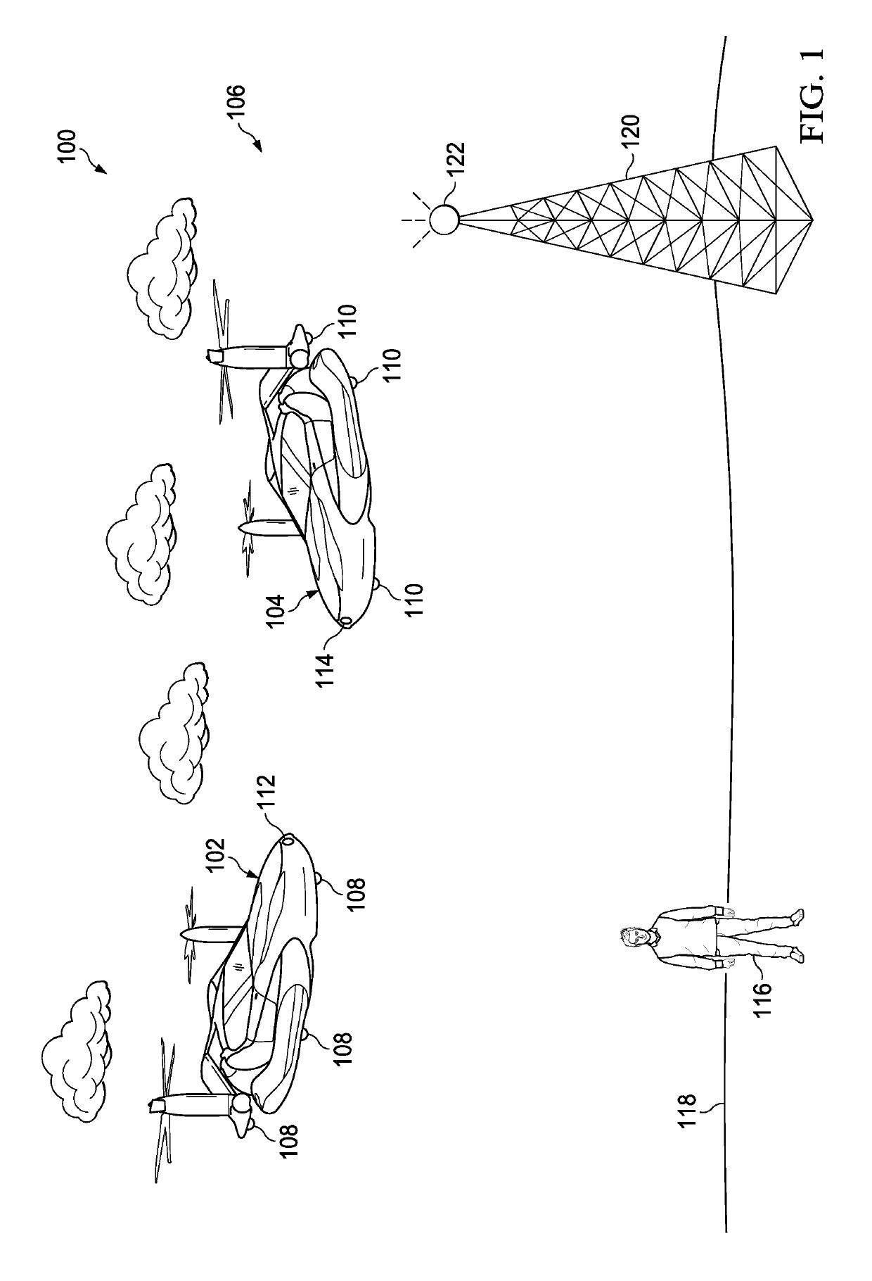
[0024]The illustrative embodiments recognize and take into account one or more different considerations. For example, the illustrative embodiments recognize and take into account that in addition to sight pollution from increased density of aircraft in areas such as cities, this increased density also can increase issues in avoiding collisions. The illustrative embodiments recognize and take into account that for piloted aircraft, detecting and avoiding collisions can rely on human vision. The illustrative embodiments also recognize and take into account that with advanced aircraft, cameras may be used in collision detection systems to avoid collisions with other aircraft or objects.

[0025]The illustrative embodiments recognize and take into account that current techniques include implementing navigation lights and flashing lights on aircraft. The illustrative embodiments recognize and take into account that these flashing lights are seen as flashing by people which can increase sigh...


PUM


Abstract

A method, apparatus, and system for automating detection and avoidance for an aircraft. A process activates a set of lamps visible on an exterior of an aircraft to emit light. The process modulates an intensity of light from the set of lamps at a set of frequencies that is detectable by a remote collision avoidance system in a remote aircraft during flight. The light from the set of lamps at the set of frequencies is perceived as continuous by a person looking at the aircraft in a sky, reducing visibility of the aircraft in the sky.

Description

BACKGROUND INFORMATION1. Field[0001]The present disclosure relates generally to an improved aircraft and, in particular, to a lighting system for the aircraft.2. Background[0002]Aircraft are commonly used for long distance transportation between cities, states, or countries. People commonly employ aircraft for personal and business travel. Additionally, many companies also transport cargo using aircraft.[0003]The wide use of aircraft has an environmental impact. Aircraft engines emit air pollution in the form of heat, noise, particulates, and gases which can affect the environment. Even with reductions in emissions from automobiles and more efficient aircraft, the rapid growth of air travel has contributed to an increase in pollution that is attributable to the air travel.[0004]Further, with advances in efficiency and innovations for engines, airframes, and aerodynamics to reduce air pollution, new types of air travel enabled by these advances and innovations can result in new types...

Claims


Application Information

Patent Timeline
Patent Type & Authority Patents(United States)
IPC IPC(8): H05B33/00B64D47/06B64D7/00B64D47/08B64D45/00H04B10/548B64C29/00H04L29/08B64C39/02B64C27/00
CPCB64D7/00B64D45/00B64D47/06H05B47/105B64D47/08H04B10/548B64C27/00B64D2045/0095B64C39/024B64C2201/22H04L67/12B64C29/00H05B47/165B64F1/20H04B10/1123H04B10/116Y02B10/30B64U20/10
Inventor TILLOTSON, BRIAN J.
Owner THE BOEING CO
Why Eureka
Try Eureka