Fastening structure and method for fitting a coupling profile to a pitched roof covered with shingles

a technology of coupling profile and pitched roof, which is applied in the direction of solar heat collector mounting/support, solar panels for particular environments, photovoltaics, etc., can solve the problems of conventional roof hooks, solar panels or supporting structures, and achieve the effects of preventing water leakage, limiting water load, and relatively limited protuberance width

Active Publication Date: 2020-02-04
ESDEC
View PDF11 Cites 20 Cited by
  • Summary
  • Abstract
  • Description
  • Claims
  • Application Information

AI Technical Summary

Benefits of technology

[0008]The top side of the fastening plate is configured to be at least partially covered by at least one bituminous shingle situated above. Usually, said top side is only partially covered during use, wherein, in particular, the first end side is substantially covered by one or more shingles situated above, and wherein the second end side is not covered by shingles. Leaving the second end side free facilitates water drainage, which further reduces the risk of water leakage via the passage opening.
[0010]In a preferred embodiment, the at least one drainage channel substantially completely protects the at least one passage opening from the first end side. Therefore, water which flows from the first end side in the direction of the second end side will only be able to reach the passage opening if the water passes and crosses over the drainage channel. This barrier prevents water from easily being able to flow in the direction of the passage opening, which prevents the occurrence of a water leakage. Preferably, the at least one passage opening is at least partially surrounded by the at least one drainage channel. Possibly, several drainage channels oriented substantially parallel to one another may be used in order to further increase the water barrier and therefore further reduce the chance of water leakage occurring.
[0012]The protruding structure (or protuberance) arranged or provided on the bottom side of the fastening plate is preferably provided with a substantially convex and / or tapering surface. Such a shape of the surface of the protruding structure which is turned towards bitumen shingles situated underneath usually makes it easier to push at least a part of the protruding structure into the shingles situated underneath, in order to bring about a substantially waterproofing (water-retaining) interaction. It is advantageous if the width of the protuberance is relatively limited, and is preferably between 1 and 10 millimetres, preferably between 3 and 7 millimetres. Such a limited width of the protuberance usually also benefits the effective depression of the shingles situated underneath.
[0013]The width of the drainage channel is usually related to the above-mentioned width of the protruding structure, and is preferably between 1 and 10 millimetres, preferably between 3 and 7 millimetres. Such dimensions are usually sufficient in order to adequately drain rainwater, for the purpose of preventing water leakage. The drainage channel is preferably situated at a distance from longitudinal edges of the fastening plate. Such a distal positioning of the drainage channel prevents water from easily being able to flow into the drainage channel via the longitudinal edges, which helps to limit the water load on the fastening plate.
[0015]The invention also relates to an assembly of a fastening structure according to the invention, and at least one coupling profile, in particular for fastening solar panels, and at least one fastening element, wherein the at least one coupling profile is fastened to the fastening structure by means of the at least one fastening element. The coupling profile may, for example, be formed by an angle profile and / or U profile. The coupling profile may be provided with coupling elements for coupling a supporting rail for solar panels to the coupling profile. It is also conceivable for coupling elements to be configured for (direct) coupling to one or more solar panels. The fastening element may form an integral part of the coupling profile, but usually a separate component is used for the fastening element. In this case, it is conceivable, for example, for the fastening element to comprise a screw and / or bolt, configured for penetration of a roof. The assembly preferably also comprises a roof covered with bituminous shingles, wherein the fastening structure is fastened to the roof by means of the at least one fastening element. In this case, the fastening plate preferably rests on at least one shingle situated underneath, and wherein at least one shingle situated above substantially completely covers the first end side of the fastening plate. It is usually advantageous if the assembly comprises at least one sealing ring, which is positioned around and / or on the peripheral wall of the passage opening of the fastening plate, wherein the total height of the at least one sealing ring is greater than or equal to the height of the above-mentioned peripheral wall, and wherein the fastening element is configured to interact with at least one sealing ring. Using such a sealing ring usually benefits the water-retaining capabilities of the assembly.

Problems solved by technology

If it is desired to fasten solar panels to a roof covered with bituminous shingles, conventional roof hooks, as described for example in NL1028379, are not suitable.
Simply screwing the solar panels or a supporting structure supporting the solar panels to a roof is also not an option, since this will perforate the bituminous roof covering, which leads to considerable water leakage.

Method used


Image

  • Fastening structure and method for fitting a coupling profile to a pitched roof covered with shingles
  • Fastening structure and method for fitting a coupling profile to a pitched roof covered with shingles
  • Fastening structure and method for fitting a coupling profile to a pitched roof covered with shingles

Examples


Embodiment Construction

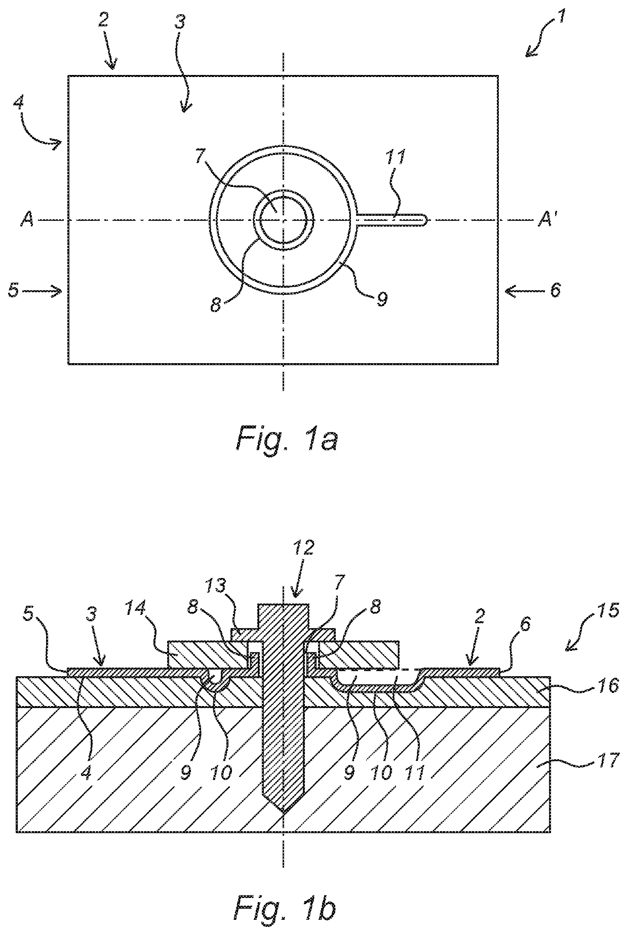
[0028]FIG. 1a diagrammatically shows a top view of a fastening structure (1) according to the invention. The fastening structure (1) comprises a fastening plate (2) with a top side (3) and a bottom side (4), and a first end side (5) and a second end side (6), and a passage opening (7) which is arranged in the fastening plate (2) and connects the bottom side (4) and the top side (3) of the fastening plate (2),

[0029]wherein the passage opening (7) is completely surrounded by a peripheral wall (8) which projects upwards with respect to a surface covered by the fastening plate (2), wherein a sunken drainage channel (9) is arranged in the top side (3) of the fastening plate (2). In this case, the upwardly projecting peripheral wall (8) forms a first water-retention feature. A second water-retention feature is formed by the drainage channel (9), which is partially circular and completely surrounds the passage opening (7). In this case, the drainage channel (9) comprises a substantially li...


PUM


Abstract

The invention relates to a fastening structure for being able to fit a coupling profile, in particular for fastening solar panels, to a pitched roof covered with bituminous shingles. The invention also relates to an assembly which includes a fastening structure according to the invention. The invention further relates to a kit of components which includes a fastening structure according to the invention. The invention further relates to a method for fitting a coupling profile, in particular for fastening solar panels, to a pitched roof covered with bituminous shingles, by using a fastening structure according to the invention.

Description

CROSS-REFERENCE TO RELATED APPLICATION[0001]This application claims priority to Dutch Patent Application No. 2018410 filed Feb. 23, 2017, the disclosure of which is hereby incorporated in its entirety by reference.BACKGROUND OF THE INVENTIONField of the Invention[0002]The invention relates to a fastening structure for being able to fit a coupling profile, in particular for fastening solar panels, to a, preferably pitched, roof covered with bituminous shingles. The invention also relates to an assembly which comprises a fastening structure according to the invention. The invention further relates to a kit of components which comprises a fastening structure according to the invention. The invention further relates to a method for fitting a coupling profile, in particular for fastening solar panels, to a pitched roof covered with bituminous shingles, by using a fastening structure according to the invention.Description of Related Art[0003]Bituminous shingles are regularly used as a roo...

Claims


Application Information

Patent Timeline
Patent Type & Authority Patents(United States)
IPC IPC(8): F24S40/44E04D1/36F24S20/67E04D1/34F24S25/60H02S20/23F24S25/613F24S20/00
CPCF24S25/613E04D1/34F24S40/44H02S20/23E04D1/365F24S20/67E04D2001/3473F24S2020/13E04D2001/3414E04D2001/3455F24S2025/6002F24S25/61F24S2025/6005Y02B10/20Y02E10/50Y02E10/47Y02B10/10
Inventor DE VOGEL, VINCENTDE VOGEL, JEROEN
Owner ESDEC
Why Eureka
Try Eureka