Devices and methods for treating conditions caused by affarent nerve signals
a technology of affarent nerve and nerve signal, which is applied in the field of devices and methods for treating conditions caused by affarent nerve signals, can solve the problems of relative invasiveness, few physicians have adopted, and use of rudimentary surgical tools, and achieves the effect of less invasive and convenient operation
- Summary
- Abstract
- Description
- Claims
- Application Information
AI Technical Summary
Benefits of technology
Problems solved by technology
Method used
Image
Examples
first embodiment
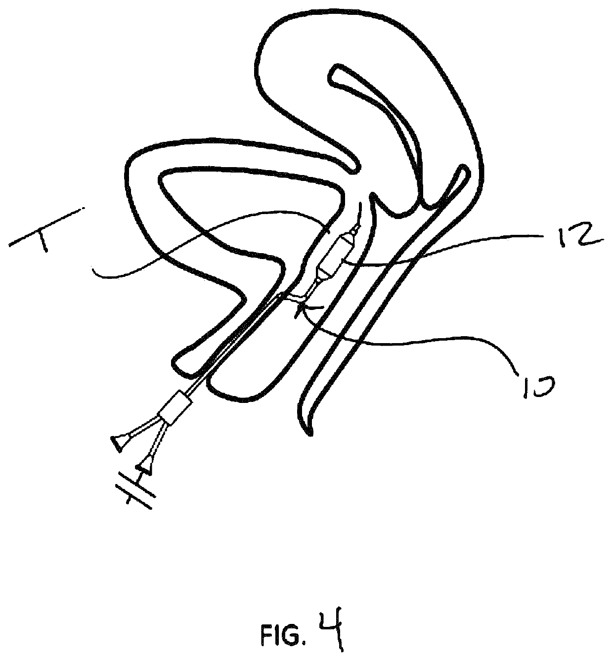
[0031]a method of the invention shown in FIG. 4. Here, a balloon catheter 10 is placed in the submucosal tissue in the trigone region T. Upon inflation (using suitable inflation medium such as liquid or air), a dilated balloon 12 forms a dissection plane within the tissue, thus disrupting the afferent nerves therein. The balloon is then deflated and removed, resulting in the dissection layer 14 shown in FIG. 5. The balloon catheter 10 may be positioned in one or multiple locations. FIG. 6 shows the resultant dissected regions 14 of multiple placements and dilations. Multiple regions may be parallel, or “fanned out”, as shown. The dissected regions or planes 14 may overlap, or be discontinuous (as shown). The size of the dissected plane(s) may be influenced by the balloon size, as well the number and position of the placements. The dissected plane(s) may be completely within the trigone region T, or may extend beyond the trigone region T. One or more dissected planes 14 may also be o...
embodiment 50
[0043]FIGS. 18-19 show another embodiment 50 of a cutting device. Here, the blades 52 may be relatively long, and as such may create a larger dissection plane 14 in the submucosal surface when the blades are opened laterally, as shown in FIGS. 18-20.
[0044]As with the balloon embodiments, these cutting device embodiments may also be used from the vaginal side of the bladder trigone to create one or more submucosal dissection planes.
embodiment 60
[0045]FIGS. 21-25 illustrate yet another alternative embodiment 60 for a cutting tool. Here cutting tool 60 may include a positioning guide 62. Positioning guide 62 may include a suction paddle 64 for engagement with the bladder mucosa, and a cutting blade 66 (shown retracted) within a cutting blade lumen 68, and a visualization device 70 such as an endoscope.
[0046]In operation, the positioning guide 62 is placed into the bladder transurethrally to a site of interest, such as adjacent the trigone region. If a dissection plane is to be made, the suction paddle 64 is placed against the bladder mucosa in the region to be submucosally dissected. Note that the endoscope 70 may be movable longitudinally within the scope channel 72 to help with precise placement of the distal tip of the suction paddle 64, as seen in FIG. 26. Advancing the endoscope 70 to near the tip can be particularly advantageous to accurately position the tip relative to the ureteral orifices in order to avoid damage t...
PUM
 Abstract
Description
Claims
Application Information
 - R&D
- Intellectual Property
- Life Sciences
- Materials
- Tech Scout
- Unparalleled Data Quality
- Higher Quality Content
- 60% Fewer Hallucinations
Browse by: Latest US Patents, China's latest patents, Technical Efficacy Thesaurus, Application Domain, Technology Topic, Popular Technical Reports.
© 2025 PatSnap. All rights reserved.Legal|Privacy policy|Modern Slavery Act Transparency Statement|Sitemap|About US| Contact US: help@patsnap.com


