Supercharge Your Innovation With Domain-Expert AI Agents!

Speed clamp for T-slotted structural elements

a technology of mechanical clamps and structural elements, applied in the field of mechanical clamps, can solve the problems of complex clamp blocks and clamp stops, inability to adjust the position of the clamp, so as to facilitate manual rotation of the position fixing mechanism

Active Publication Date: 2020-02-11
FORTISCLAMP LLC
View PDF50 Cites 1 Cited by
  • Summary
  • Abstract
  • Description
  • Claims
  • Application Information

AI Technical Summary

Benefits of technology

The present invention allows for easy positioning of a clamp block on a slotted structural element. The clamp block has a continuous adjustment slot within which a component can be located. The clamp includes a positioning hole and a horizontal passage through which a fixing pin is inserted, and a slidable feature that moves within the T-slot channel. A position fixing mechanism applies an upward force on the fixing pin to secure the clamp block in place. The clamping shaft is advanced and withdrawn by simple rotation and can be fixed at a desired location by pressing a quick nut. The body of the clamp block rotates 360 degrees and the end closest to the work piece includes a pivoting pad or a clamp stop that does not interfere with sliding of the clamp block along the T-channel.

Problems solved by technology

Unfortunately, traditional clamps used for interconnecting structural members such as strut channels and slotted extrusions suffer from several deficiencies.
Also, known clamp blocks and clamp stops are typically complex, and require advanced manufacturing techniques to construct, and the number of clamp blocks and clamp stops that can be attached to a given structural member is very limited.
In addition, structural members to which clamps are attached are typically dedicated to the function of the clamp and cannot be easily used in other applications, due to the fastening or welding of the clamp components to the said structural member and / or structural changes made to the structural member itself to accommodate the clamps.
As a result, other structural members and / or additional accessories are not easily attached to the clamp structure, which limits the function of the clamp.
Known strut clamps also set a lower-limit on the cross-sectional size of the strut channels with which they are compatible, typically requiring U-shaped channels of the larger variety, because smaller or more shallow U-shaped channels do not provide sufficient cross-sectional area for attachment of known clamp designs.

Method used


Image

  • Speed clamp for T-slotted structural elements
  • Speed clamp for T-slotted structural elements
  • Speed clamp for T-slotted structural elements

Examples


Embodiment Construction

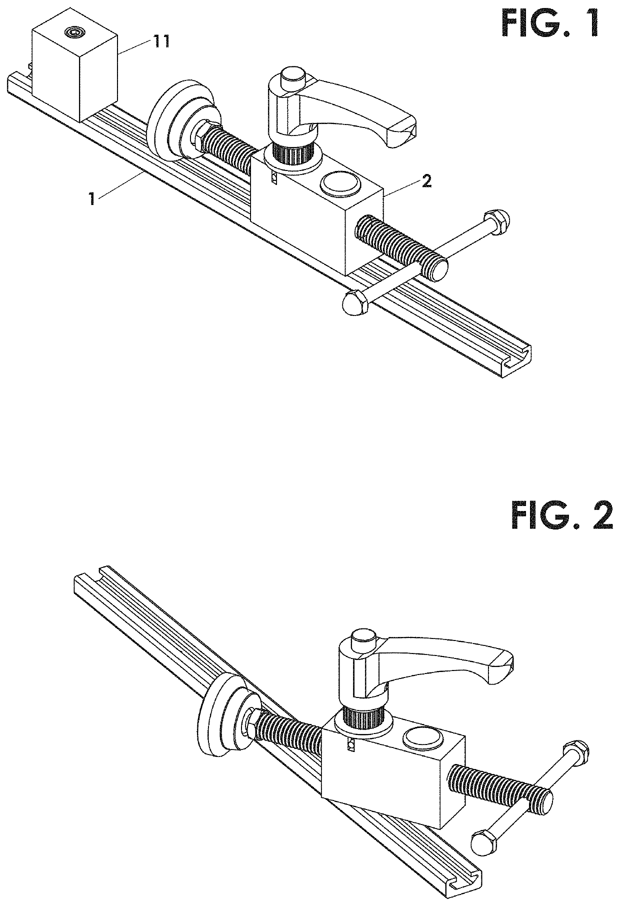
[0078]FIG. 1 is a perspective view of an embodiment with a clamp block, also referred to herein as a clamp housing 2, having a smooth, flat bottom surface. The clamp housing 2 and the clamp stop 11 are shown attached to a T-slotted extrusion 1. Other configurations of slotted extrusion are available in the industry, and are compatible with the present invention so long as the slot includes an overhang on both sides thereof. The slotted extrusion shown in this figure is a style that is commercially available from many “T” slot extrusion manufacturers. The “T” style slot allows the clamp housing 2 and clamp stop 11 to be mounted anywhere along the length of the slotted extrusion.

[0079]FIG. 2 shows the ability of the clamp housing 2 of FIG. 1 to rotate 360 degrees on the T-slotted structural element 1.

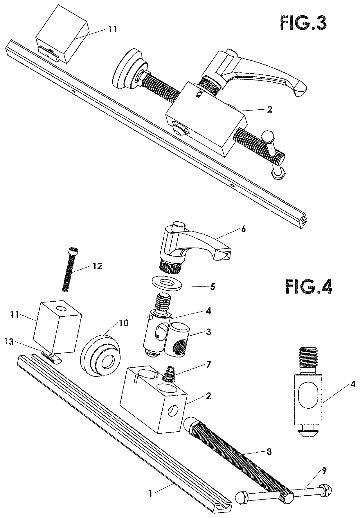
[0080]FIG. 3 is a partially exploded view of the embodiment of FIG. 1 showing the flat bottom surface of clamp housing 2 and clamp stop 11.

[0081]FIG. 4 is an exploded view of FIG. 3. The ...


PUM


Abstract

A clamp for a T-slotted structural element can be positioned anywhere along the T-slot. A housing and stop are opposingly attached to the structural member, and a horizontal shaft is engaged with the housing. A fixing pin is inserted through a vertical hole in the housing and attached to a slot key that is inserted in the T-slot. Actuating a lever or handle applies an upward force on the fixing pin, pressing the key against the top of the T-slot and fixing the housing in place. In embodiments, the stop can be repositioned to any of a plurality of locations along the T-slot. In certain embodiments, the stop and housing can be placed on different surfaces of the structural member. In various embodiments, the stop and / or housing are constructed with different slot profiles that match their respective T-slotted structural elements. In embodiments, the housing is rotatable.

Description

RELATED APPLICATIONS[0001]This application is a continuation in part of U.S. patent application Ser. No. 15 / 640,998 filed Jul. 3, 2017. Application Ser. No. 15 / 640,998 claims the benefit of U.S. Provisional Application No. 62 / 493,543, filed Jul. 8, 2016, which is herein incorporated by reference in its entirety for all purposes.FIELD OF THE INVENTION[0002]The invention relates to mechanical clamps, and more particularly, to mechanical clamps that are mounted to a structural member.BACKGROUND OF THE INVENTION[0003]Slotted structural elements that are used in the construction and electrical industries for light structural support, often for supporting wiring, plumbing, or mechanical components such as air conditioning or ventilation systems.[0004]One, less expensive type of slotted structural element is a channeled strut, which is usually formed from metal sheet, folded over into an open channel shape with inward-curving edges to provide additional stiffness and as a location to mount...

Claims


Application Information

Patent Timeline
IPC IPC(8): B25B5/16B25B5/10B25H1/18
CPCB25B5/166B25B5/10B25H1/18B25B1/103B25B5/006B25B5/02B25H1/00
Inventor KELLY, MICHAEL T.
Owner FORTISCLAMP LLC
Features
  • R&D
  • Intellectual Property
  • Life Sciences
  • Materials
  • Tech Scout
  • Unparalleled Data Quality
  • Higher Quality Content
  • 60% Fewer Hallucinations
Learn More