Trajectory determination method for non-productive movements

a non-productive movement and trajectory determination technology, applied in the direction of programmed manipulators, programme control, instruments, etc., can solve the problems of considerable time and energy savings in performing a non-productive movement, and achieve the effect of optimizing the non-productive movement and reducing the computing power and requirements of the hardware used

Active Publication Date: 2020-02-11
SIEMENS AG
View PDF31 Cites 0 Cited by
  • Summary
  • Abstract
  • Description
  • Claims
  • Application Information

AI Technical Summary

Benefits of technology

[0032]An increment for the modification to the correction condition is preferably detected on the basis of the overshoot distance. The greater is the overshoot distance, the greater is the increment during modification of the correction condition. As a result, as a function of the extent of the required correction to a previously calculated first and second trajectory, a corrective action or modification of a corresponding extent is made. The method according to the invention is, as a result, dynamically adaptable. Consequently, the at least one optimized trajectory which is required for an optimized non-productive movement may be established in a small number of runs of the method even in the event of strong filter effects. The necessary computing power and requirements placed on the hardware used are thus reduced.
[0033]The object of the invention is furthermore achieved by a program which serves to control a tool in a machine tool. The machine tool comprises at least one drive means which brings about a tool movement. This is preferably an electric motor for producing a translational or rotational movement of the tool. The program according to the invention is configured to execute at least one embodiment of the claimed trajectory determination method. The program furthermore outputs the at least one reference variable which has been established to the drive means such that the optimized non-productive movement is performed. The program according to the invention may replace or supplement existing tool control software as an update. As a result, the claimed path control method can be performed simply with an existing tool.

Problems solved by technology

Using a pathfinding algorithm achieves considerable time and energy savings in performing a non-productive movement.

Method used


Image

  • Trajectory determination method for non-productive movements
  • Trajectory determination method for non-productive movements
  • Trajectory determination method for non-productive movements

Examples


first embodiment

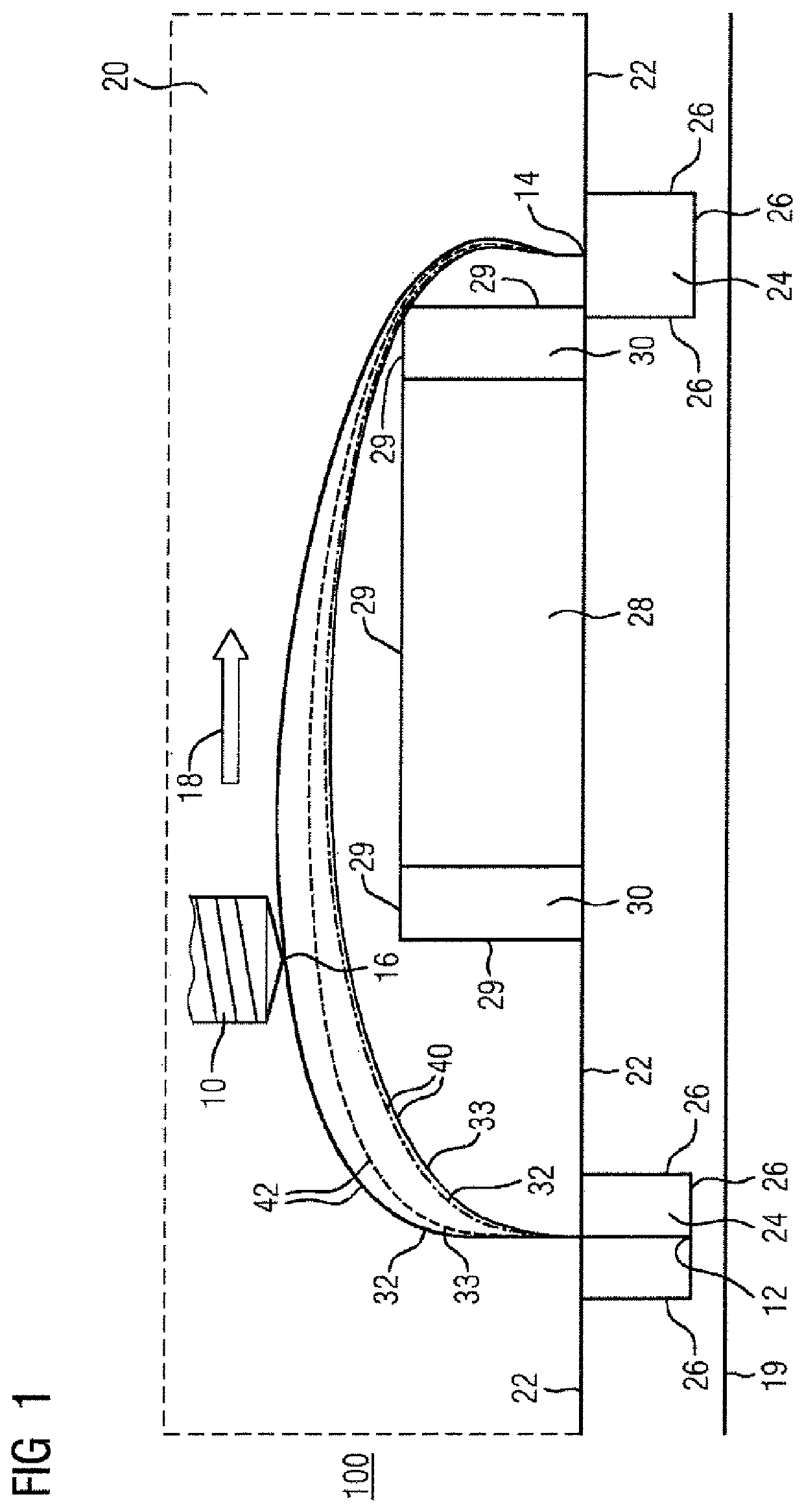
[0040]FIG. 1 shows the method 100 according to the invention in a side view. The task addressed by the method 100 is depicted in FIG. 1 as a planar projection of a spatial task. A tool 10 here moves in a travel envelope 20 which corresponds to the entire space which is accessible to the tool 10 without collision. In FIG. 1, the tool 10 is performing a non-productive movement which substantially proceeds in an overall direction of movement 18. The tool 10 is guided from the region of a recess 24 at a starting position 12 to the region of a recess 24 at a target position 14. The recesses 24 are provided in a workpiece contour 22 which extends substantially horizontally. The recesses 24 are furthermore bounded by walls 26 which adjoin one another.

[0041]The coordinates perpendicular to the illustrated overall direction of movement 18 are defined for the non-productive movement according to FIG. 1 relative to a reference plane 19. Tool reference point 16, which is substantially located a...

second embodiment

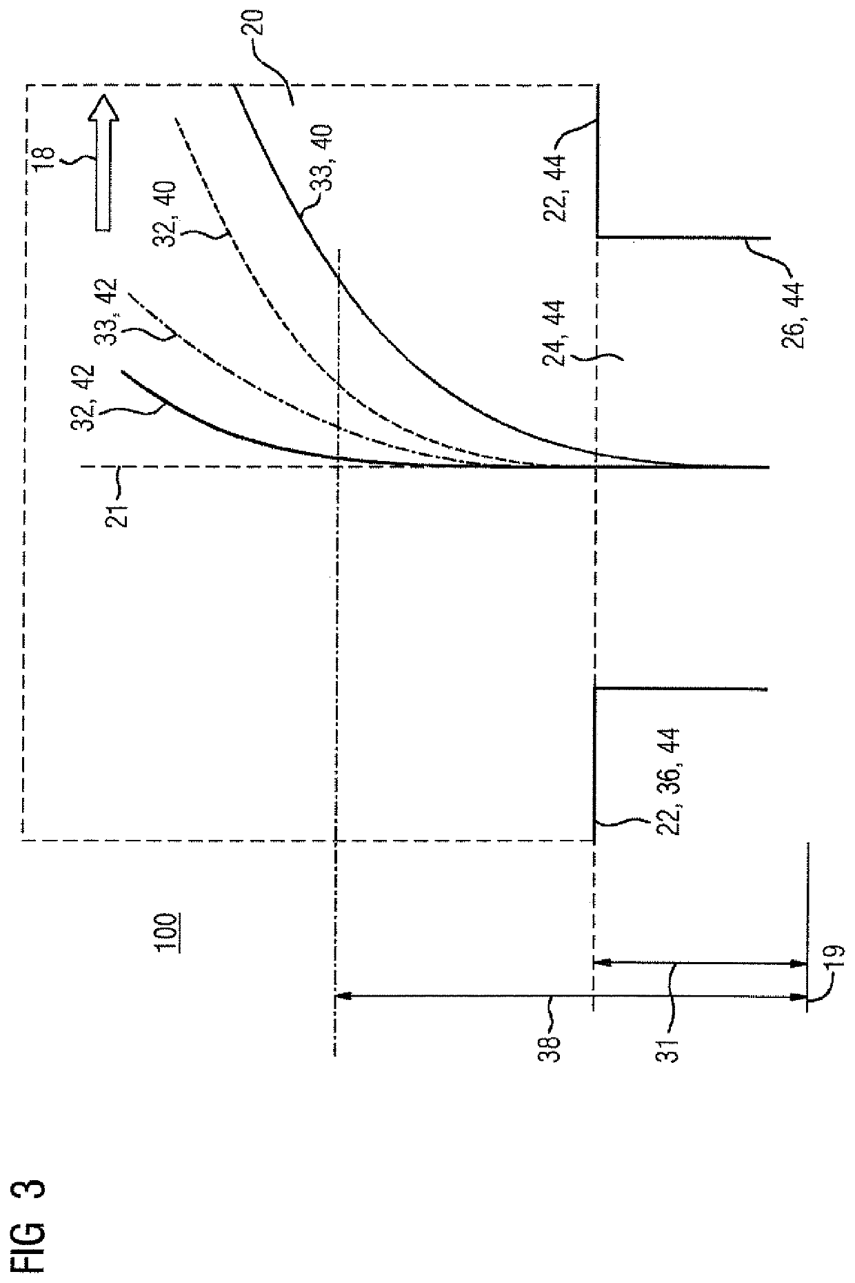
[0048]FIG. 3 depicts a detail view of the method 100 according to the invention. The tool 10, not shown in greater detail, is being moved away from a starting position 12 in the region of a recess 24 in the workpiece contour 22. The tool 10 is here being moved in the travel envelope 20 which substantially corresponds to the clear space which is accessible without collision. The movement to a target position 14, not shown in greater detail, substantially proceeds along an overall direction of movement 18. The recess 24 bounded by walls 26 corresponds to a bore which is formed in the workpiece. The workpiece contour 22 and the walls 26 are here rigid constraints 44 which each define collision conditions. In the first run 40 of the pathfinding algorithm, a first trajectory 32 is established, in which, starting from the starting position 12, movement initially merely proceeds along a reference axis 21. The first trajectory 32 is located in the region of the recess 24 on the reference ax...


PUM


Abstract

The invention relates to a method (100) for determining an optimised trajectory for a non-productive movement of a tool (10) of a machine tool, from a starting position (12) to an end position (14). The non-productive movement is carried out in a spatially restricted travelling area (20) which is represented by geometric conditions. The method according to the invention is executed with the avoidance of collisions and comprises the step of determining a first trajectory (32) of the tool (10) by means of a travel-finding algorithm. In this step, the first trajectory (32) is optimised for the non-productive movement with respect to at least one selectable target parameter.

Description

CROSS-REFERENCES TO RELATED APPLICATIONS[0001]This application is the U.S. National Stage of International Application No. PCT / EP2016 / 062588, filed Jun. 3, 2016, which designated the United States and has been published as International Publication No. WO 2017 / 005428 and which claims the priority of European Patent Application, Serial No. 15176108.7, filed Jul. 9, 2015, pursuant to 35 U.S.C. 119(a)-(d).BACKGROUND OF THE INVENTION[0002]The invention relates to a method for determining a trajectory for a non-productive movement of a tool and to a corresponding program. The invention furthermore relates to a machine tool with at least one tool which is configured to implement the method according to the invention.[0003]WO 2012 / 069129 A1 discloses a method for controlling a robot system in which a plurality of robots perform working steps in coordinated manner. The individual working steps here comprise segments which are separately optimized with regard to the segment time required the...

Claims


Application Information

Patent Timeline
Patent Type & Authority Patents(United States)
IPC IPC(8): G05B19/4061G05B19/4069B25J9/16G05B19/404G05B19/414
CPCG05B19/4069B25J9/1666G05B19/4061
Inventor GEISSDÖRFER, KLAUSHAMM, CARSTENLINKE, HARTMUTSCHÄFERS, ELMAR
Owner SIEMENS AG
Why Eureka
Try Eureka