Hollow fan blade constrained layer damper

a technology of damper and fan blade, which is applied in the direction of machines/engines, mechanical equipment, liquid fuel engines, etc., can solve the problems of reducing the life of the fan blad

Active Publication Date: 2020-02-11
RTX CORP
View PDF20 Cites 2 Cited by
  • Summary
  • Abstract
  • Description
  • Claims
  • Application Information

AI Technical Summary

Problems solved by technology

These elevated vibratory stresses can exceed fatigue capability resulting in reduced fan blade life.

Method used


Image

  • Hollow fan blade constrained layer damper
  • Hollow fan blade constrained layer damper
  • Hollow fan blade constrained layer damper

Examples


Embodiment Construction

[0030]A detailed description of one or more embodiments of the disclosed apparatus and method are presented herein by way of exemplification and not limitation with reference to the Figures.

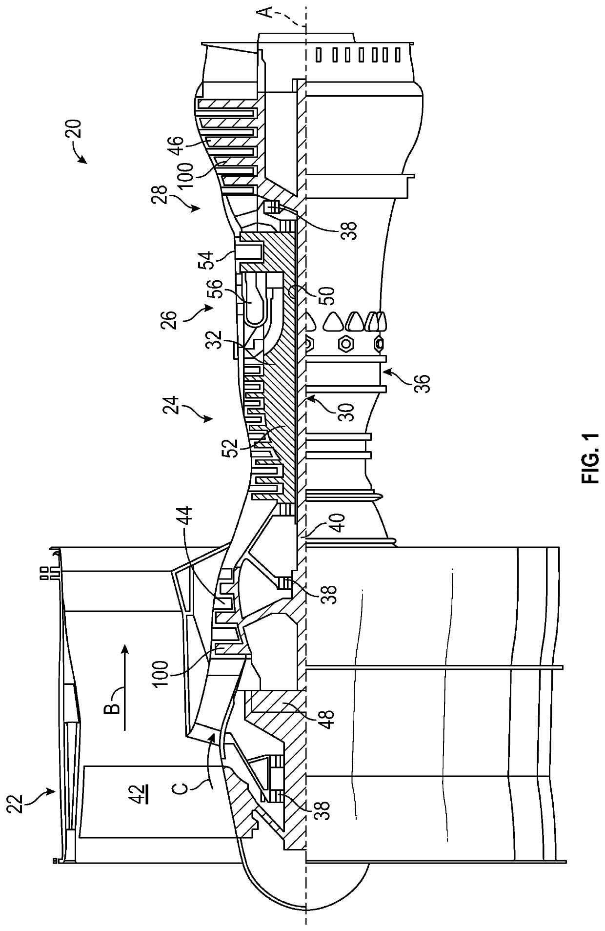
[0031]The environment in which fan blades operate can create high dynamic stress. Sources of the high stress include inlet distortion, flutter and post bird ingestion run-on for the diversion mission. Inlet distortion stress can be created by several sources, including inlet geometry, cross wind, inlet separation and inlet vortices. These elevated vibratory stresses can exceed fatigue capability resulting in reduced fan blade life.

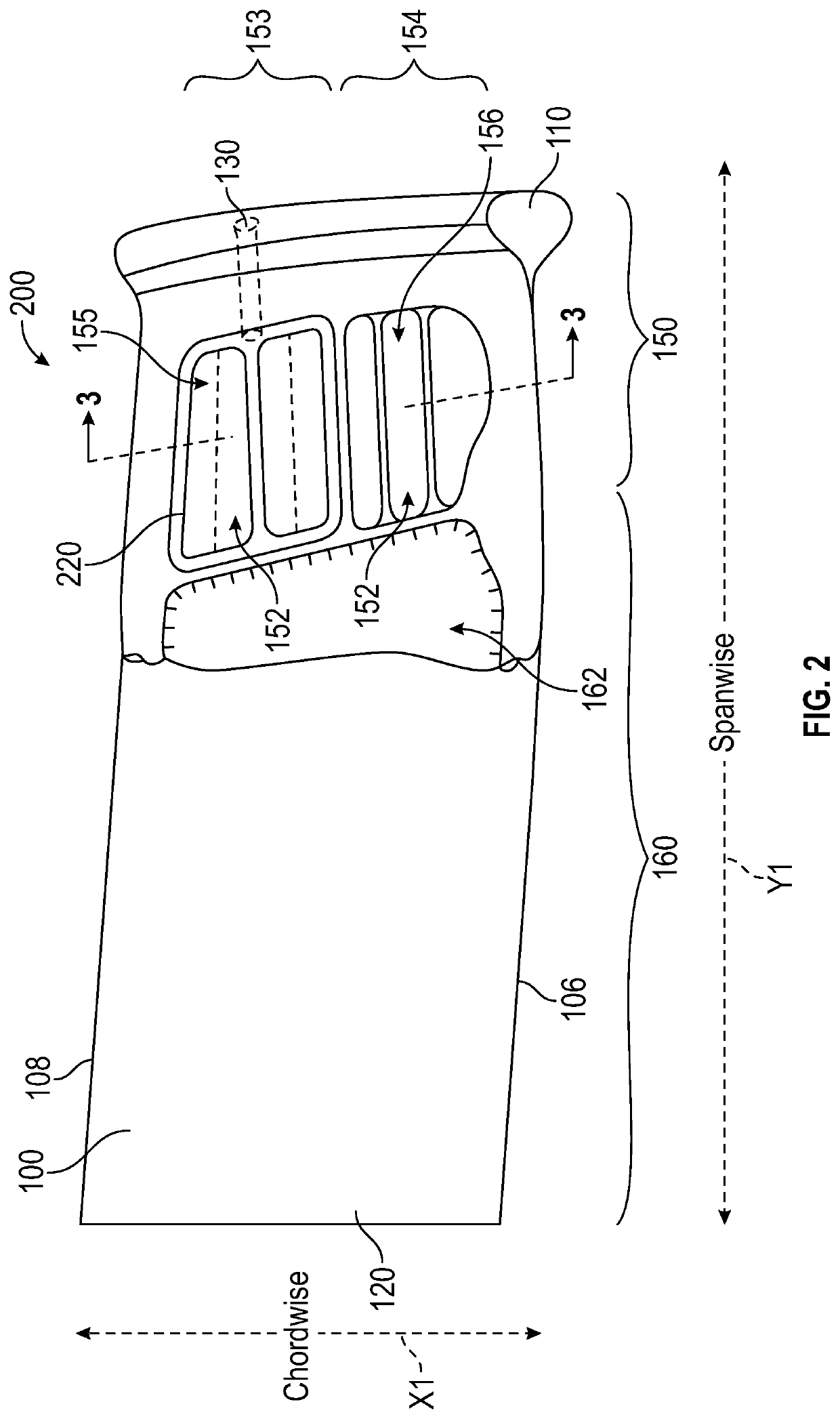
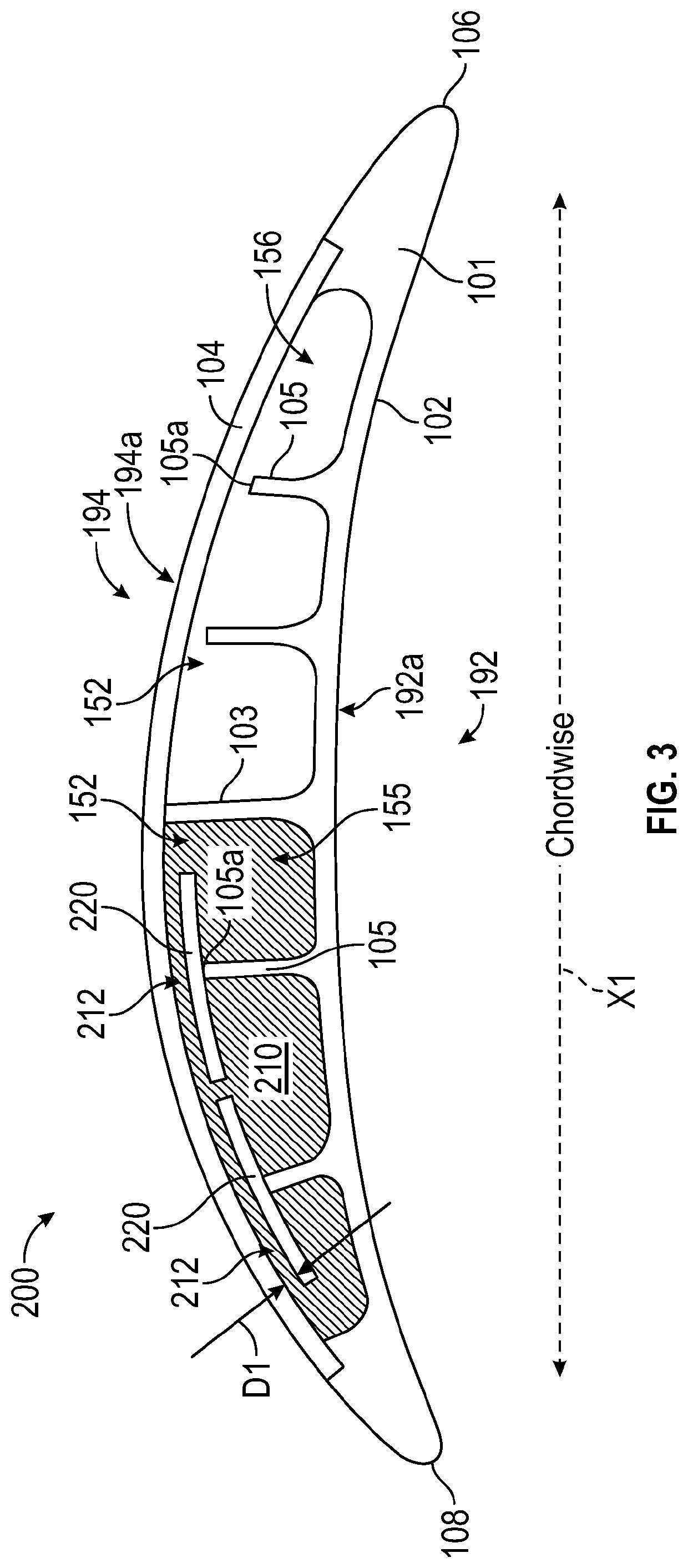
[0032]Embodiments disclosed herein include apparatuses and methods to attenuate high vibratory stress in a hollow airfoil design. A hollow airfoil, which can be a stator or rotor, typically has internal structure to provide stiffness for static and vibratory loading design requirements. Advantageously, a hollow airfoil allows a damping system to be incorporated internal...


PUM


Abstract

A fan blade having a damping system is provided. The fan blade comprising: a fan blade body having one or more compartments within the fan blade body; a damping material located within at least one of the one or more compartments; one or more partial ribs originating at the fan blade body and extending into at least one of the one or more compartments, wherein each of the one or more partial ribs terminate at a distal end; and one or more damping plates, wherein each of the one or more damping plates are attached to a distal end of a partial rib, wherein the damping material is located between the damping plate and the fan blade body.

Description

BACKGROUND[0001]The subject matter disclosed herein generally relates to fan blades in gas turbine engines and, more particularly, to a method and apparatus for damping blades of gas turbine engines.[0002]The environment in which fan blades operate can create high dynamic stress. Sources of the high stress include inlet distortion, flutter and post bird ingestion run-on for the diversion mission. Inlet distortion stress can be created by several sources, including inlet geometry, cross wind, inlet separation and inlet vortices. These elevated vibratory stresses can exceed fatigue capability resulting in reduced fan blade life.SUMMARY[0003]According to one embodiment, a fan blade having a damping system is provided. The fan blade comprising: a fan blade body having one or more compartments within the fan blade body; a damping material located within at least one of the one or more compartments; one or more partial ribs originating at the fan blade body and extending into at least one...

Claims


Application Information

Patent Timeline
Patent Type & Authority Patents(United States)
IPC IPC(8): F01D5/16F01D5/18
CPCF01D5/16F01D5/18F05D2220/36F05D2260/96F04D29/324F04D29/668Y02T50/60
Inventor MALMBORG, ERIC W.POLLACK, THOMAS A.
Owner RTX CORP
Why Eureka
Try Eureka