
Transport system, processing system, and control method of transport system

a technology of transportation system and processing system, applied in the field of transportation system, can solve the problems of large installation space required in the production line, increase in the entire time required to process work, and large installation space needs to be secured, so as to achieve the effect of increasing the size or complexity of the system configuration

Active Publication Date: 2020-02-18
CANON KK
View PDF14 Cites 4 Cited by
  • Summary
  • Abstract
  • Description
  • Claims
  • Application Information

AI Technical Summary

Benefits of technology

[0009]The present invention intends to provide a transport system and a control method thereof that can drive a movable mechanism on a carriage without involving an increase in size or complexity of the system configuration and provide a processing system having the transport system.
[0015]According to the present invention, a movable mechanism on a carriage can be driven without an increase in size or complexity of a system configuration.

Problems solved by technology

Thus, there is a problem that a wide installation space is required in the production line to arrange both a transport system and an apparatus used for changing the state of a work.
Further, the time for converting the state of a work is required during transport or immediately before processing of a work, and this results in a problem of an increase in the entire time required to process the work.
In the work transport apparatus disclosed in Japanese Patent Application Laid-Open No. 2001-179568, however, there is a problem that attitude change mechanisms need to be installed adjacent to the work transport apparatuses for respective processes and therefore a large installation space needs to be secured.
Further, when a processing position of a processing face in each process is changed, it is necessary to again adjust the installed attitude change mechanism every time, and it takes time for such adjustment.
However, position control of a plurality of movers needs to be performed along with a mover of a low moving speed, which results in a limited moving speed of a carriage.
Thus, there is a problem of increased complexity and size of a system.

Method used


Image

  • Transport system, processing system, and control method of transport system
  • Transport system, processing system, and control method of transport system
  • Transport system, processing system, and control method of transport system

Examples


first embodiment

[0037

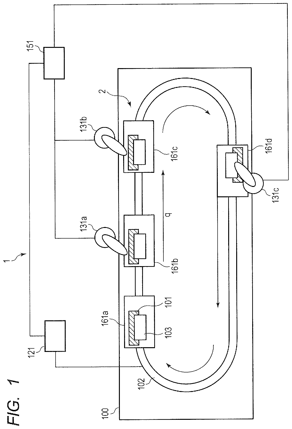
[0038]A first embodiment of the present invention will be described below with reference to the drawings. First, the entire configuration of a processing system according to the present embodiment will be described by using FIG. 1. FIG. 1 is a schematic diagram illustrating the entire configuration of the processing system according to the present embodiment.

[0039]As illustrated in FIG. 1, a processing system 1 according to the present embodiment has a transport path 102, carriages 161, process apparatuses 131, a transport controller 121, and a process controller 151. The processing system 1 according to the present embodiment includes a transport system 2 that transports works 101 to be processed. The transport system 2 has the transport path 102, the carriages 161, and the transport controller 121. FIG. 1 illustrates four carriages 161a, 161b, 161c, and 161d as the carriages 161. Further, three process apparatuses 131a, 131b, and 131c are illustrated as the process apparatuse...

second embodiment

[0121

[0122]A second embodiment of the present invention will be described by using FIG. 8A and FIG. 8B. Note that similar components to those of the first embodiment described above are labeled with the same references and the description thereof will be omitted or simplified.

[0123]The carriage 161 according to the present embodiment is different from the carriage 161 according to the first embodiment in the form of fixation of the permanent magnets 221a, 221b, and 221c. The details of the configuration of the carriage 161 according to the present embodiment will be described below by using FIG. 8A and FIG. 8B. FIG. 8A and FIG. 8B are schematic diagrams illustrating the carriage 161 and the transport path 102 according to the present embodiment, respectively. FIG. 8A is a diagram viewed from the q-axis direction, and the FIG. 8B is a diagram viewed from the p-axis direction. Note that, in FIG. 8B, a part of the casing 202 or the like that is unnecessary for the description is omitte...

third embodiment

[0129

[0130]A third embodiment of the present invention will be described by using FIG. 9A to FIG. 12. Note that similar components to those of the first and second embodiments described above are labeled with the same references and the description thereof will be omitted or simplified.

[0131]The carriage 161 according to the present embodiment is different from the carriage 161 according to the first embodiment in that the work holder 103 and the permanent magnets 221 fixed thereto are movable also in the q-axis direction. The configuration of the carriage 161 according to the present embodiment will be described below in detail by using FIG. 9A and FIG. 9B. FIG. 9A and FIG. 9B are schematic diagrams illustrating the carriage 161 and the transport path 102 according to the present embodiment, respectively. FIG. 9A is a diagram viewed from the q-axis direction, and the FIG. 9B is a diagram viewed from the p-axis direction. Note that, in FIG. 9B, a part of the casing 202 or the like t...


PUM


Abstract

A transport system includes a plurality of coils; and a carriage that has a magnet and is movable in a first direction along the plurality of coils in accordance with electromagnetic force to which the magnet is subjected from the plurality of coils, and the carriage has a movable mechanism that is provided so as to be able to interlock with the magnet and is driven by electromagnetic force to which the magnet is subjected in a second direction intersecting with the first direction from the plurality of coils.

Description

BACKGROUND OF THE INVENTION[0001]Field of the Invention[0002]The present invention relates to a transport system and a control method thereof using a movable magnet-type linear motor (a moving magnet-type linear motor, a movable magnetic field-type linear motor) and to a processing system having the transport system.[0003]Description of the Related Art[0004]In general, transport systems are used in production lines for assembling industrial products. A transport system in a production line transports a work such as a component among a plurality of stations within or between factory-automated production lines. As a transport system, a transport system with a movable magnet-type linear motor has already been proposed.[0005]In a production line, a clamp / unclamp state of a work may be changed or a processing face of a work may be changed during each working process or between the previous working process and the next working process. In such a case, the state of a work on a mover in a t...

Claims


Application Information

Patent Timeline
Patent Type & Authority Patents(United States)
IPC IPC(8): B65G54/02
CPCB65G54/02B65G2203/02B65G35/06
Inventor YAMAMOTO, TAKESHI
Owner CANON KK
Learn More