

Asymmetric axial permanent magnet machines having axial rotors with irregular magnets
a permanent magnet machine and irregular magnet technology, applied in the direction of dynamo-electric machines, magnetic circuit rotating parts, magnetic circuit shape/form/construction, etc., can solve the problem of loss of heat escape route from stator coils, and achieve high symmetry, facilitate interconnection of windings, and facilitate manufacture
- Summary
- Abstract
- Description
- Claims
- Application Information
AI Technical Summary
Benefits of technology
Problems solved by technology
Method used
Image

Examples
Embodiment Construction
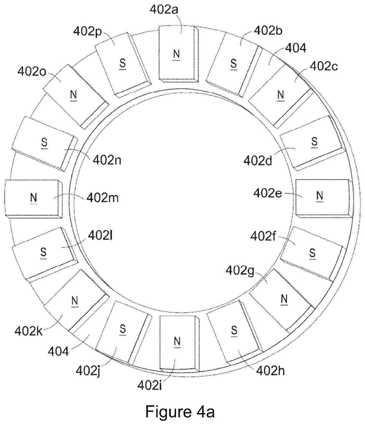
[0034]Referring to FIG. 4a this shows a first stage in design of an asymmetric rotor 400 according to an embodiment of the invention. In the illustrated example the rotor has 16 magnets 402 and is preferably employed with a stator having 24 poles. The magnets 402 are mounted on a backplate 404 which, in the illustrated example, has a ring shape. In general, however, the shape of the backplate is not critical and may depend, for example, on the driver arrangement from / to the rotor—in other arrangements, for example, the backplate 404 may be disc-shaped.
[0035]As illustrated in FIG. 4a the magnets 402 are arranged with alternating north 402a and south 402b pole faces and, at this stage in the design process, the magnets are spaced circumferentially at regular intervals around the backplate 404.
[0036]As illustrated in FIG. 4a the rotor has 8-fold symmetry. In FIG. 4b this symmetry has been broken by a pairwise displacement of the rotor magnets from their regularly spaced positions. In p...
PUM
 Abstract
Description
Claims
Application Information