Center link knife drive for a header of an agricultural harvester

a technology for harvesters and blade drives, applied in the field of agricultural harvesters, can solve the problems of difficult modification or retrofitting of complicated gearboxes for different applications, failures that are costly and time-consuming to remedy, and the seams have proved difficult to keep working properly, so as to avoid material buildup and eliminate the possibility of dir

Active Publication Date: 2020-02-25
BLUE LEAF I P INC
View PDF37 Cites 1 Cited by
  • Summary
  • Abstract
  • Description
  • Claims
  • Application Information

AI Technical Summary

Benefits of technology

In accordance with the exemplary embodiments, there is provided an exposed knife head drive assembly for a header of an agricultural harvester. When the subject disclosure is used in combination with an agricultural harvester, the disclosure overcomes one more of the disadvantages referenced above by providing a header in which the exposed or unhoused knife head drive assembly eliminates the need for an enclosed and sealed gearbox wherein the seals have proven to be difficult to keep working properly in certain conditions due to dirt accumulation. The exposed knife head drive assembly is easy to repair and comparatively easy to modify or retrofit for different applications.
Further in accordance with the exemplary embodiments, the subject disclosure provides a construction that reduces and preferably eliminates any possibility for dirt to build up and rest on the top of the seals (where seals are necessary such as at the pivot joints). This would mainly be accomplished by using rounded surfaces and avoiding the flat cover associated with the existing gearboxes. In addition, the seals would be mounted higher than any areas around them to avoid material buildup on the seals. In addition, joints used could include ball joints similar to those used on certain existing knifeheads as well as rubber bushings.

Problems solved by technology

However, existing center knife drives often include a complicated gearbox with two shafts extending upward that oscillate back and forth and drive the two knives on the header.
These seals have proven to be difficult to keep working properly in certain conditions due to dirt accumulation.
Once dirt gets past the seals and into the gearbox, bearings and other components become worn and result in failures that are costly and time-consuming to remedy.
In addition, the complicated gearbox is relatively difficult to modify or to retrofit for different applications due to its design and manufacturing method.

Method used


Image

  • Center link knife drive for a header of an agricultural harvester
  • Center link knife drive for a header of an agricultural harvester
  • Center link knife drive for a header of an agricultural harvester

Examples


Embodiment Construction

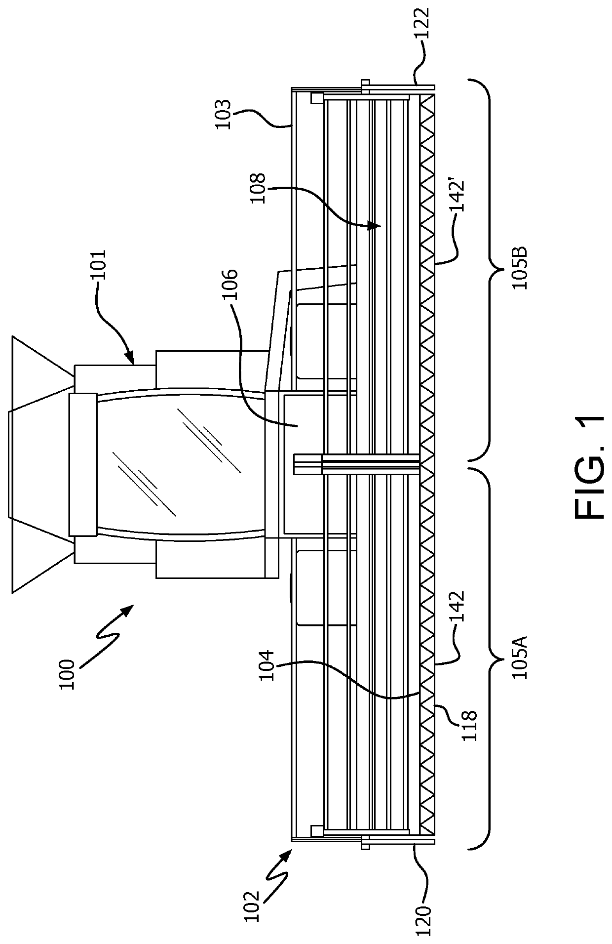
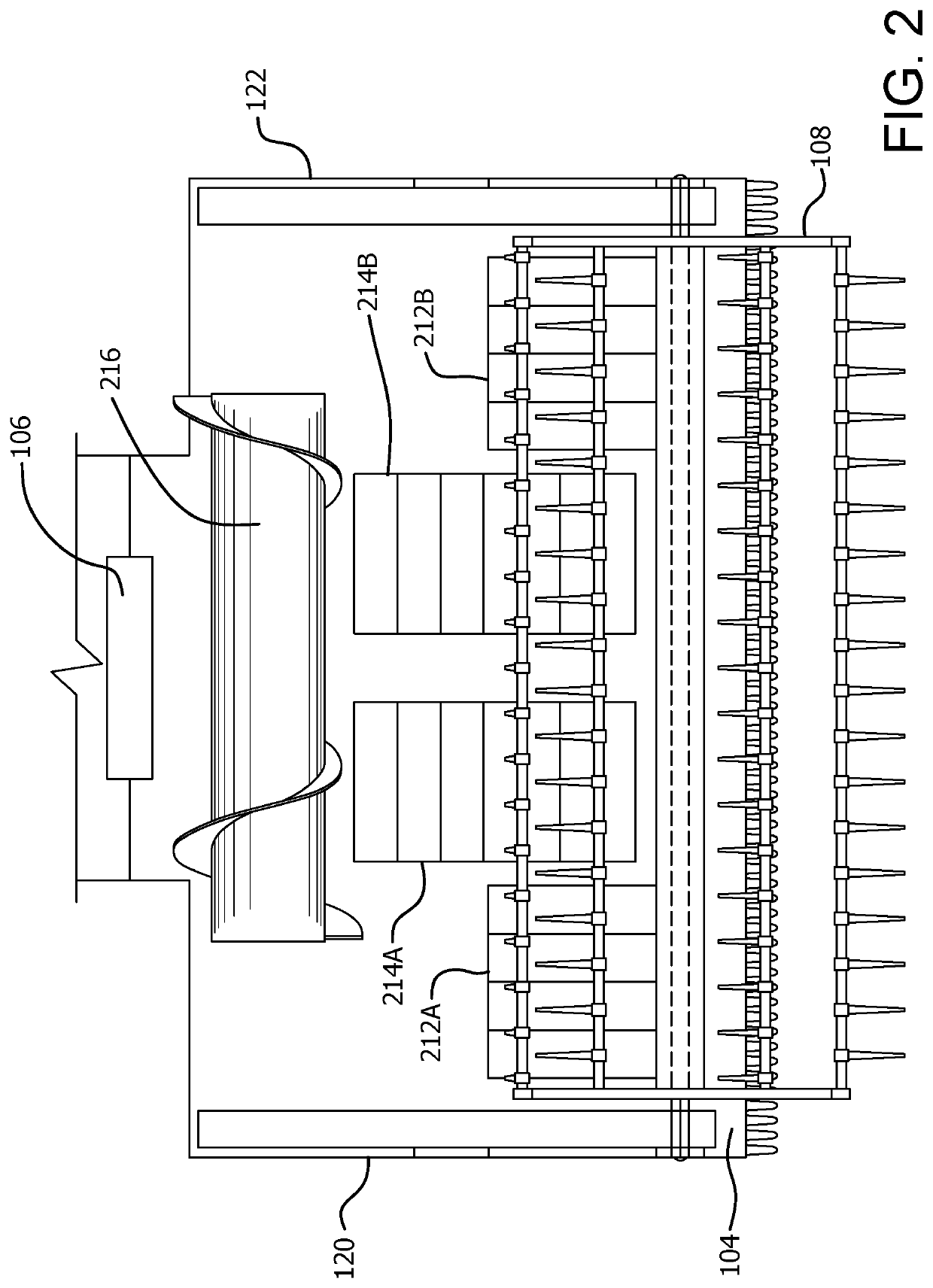
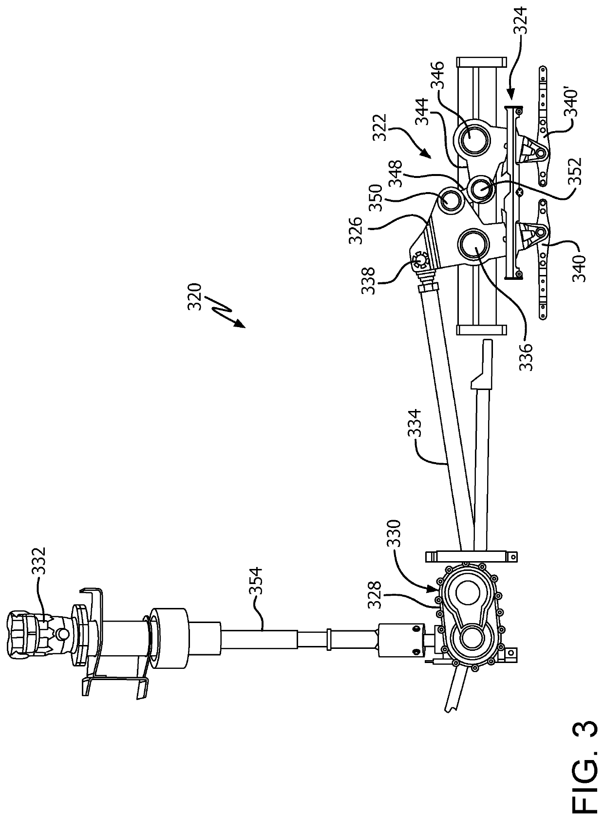
Reference will now be made in detail to the various exemplary embodiments of the subject disclosure illustrated in the accompanying drawings. Wherever possible, the same or like reference numbers will be used throughout the drawings to refer to the same or like features. It should be noted that the drawings are in simplified form and are not drawn to precise scale. Certain terminology is used in the following description for convenience only and is not limiting. Directional terms such as top, bottom, left, right, above, below and diagonal, are used with respect to the accompanying drawings. The term “distal” shall mean away from the center of a body. The term “proximal” shall mean closer towards the center of a body and / or away from the “distal” end. The words “inwardly” and “outwardly” refer to directions toward and away from, respectively, the geometric center of the identified element and designated parts thereof. Such directional terms used in conjunction with the following desc...


PUM


Abstract

A knife head drive assembly for a header of an agricultural harvester including a knife head assembly for attachment to a forward end of the header. A first pivot arm and a second pivot arm are carried by the knife head assembly and are pivotably connected by a linkage. A rotating crank is operatively connected to and extending substantially transverse to the knife head assembly for engagement with a drive. A reciprocating shaft is connected to the rotating crank and either of the pivot arms or the linkage. Operation of the knife head drive assembly results in substantially linear, opposed oscillating motion of cutter bars carried by the knife head assembly.

Description

The exemplary embodiments of present invention relate generally to a knife head drive assembly for a header of an agricultural harvester and, more specifically, to a knife head assembly having an exposed center link knife drive for driving crop cutterbars.BACKGROUND OF THE DISCLOSUREAn agricultural harvester e.g., a plant cutting machine, including, but not limited to, a powered vehicle such as a combine or a windrower, generally includes a header operable for severing and collecting plant or crop material as the harvester is driven over a crop field. The header has a plant cutting mechanism, e.g., a cutter bar, for severing the plants or crops via, for example, an elongate sickle mechanism that reciprocates sidewardly relative to a non-reciprocating guard structure. After crops are cut, they are collected inside the header and transported via at least one conveyor such as a draper belt and / or an infeed belt towards a feederhouse located centrally inside the header.Cutterbar knife d...

Claims


Application Information

Patent Timeline
Patent Type & Authority Patents(United States)
IPC IPC(8): A01D34/34A01D41/14A01D34/14
CPCA01D34/145A01D34/34A01D41/142A01D34/30
Inventor COOK, JOELHINKLE, JOHNFARLEY, HERBDECHRISTOPHER, DAVID M.LEHMAN, BARRY
Owner BLUE LEAF I P INC
Why Eureka
Try Eureka