Hybrid touch module

a hybrid touch and module technology, applied in the field of touch modules, can solve the problems of inability to smoothly operate the user may easily make a touch error, and the thickness of the product is large, so as to prevent touch errors, smooth operation of the hybrid touch module, and wide-ranging operating conditions for users

Active Publication Date: 2020-02-25
HIGGSTEC
View PDF24 Cites 0 Cited by
  • Summary
  • Abstract
  • Description
  • Claims
  • Application Information

AI Technical Summary

Benefits of technology

The advantage of the present disclosure is that the hybrid touch module of the present disclosure is capable of providing the resistive touch function by virtue of the common layer structure in cooperation with the bottom layer structure, and is capable of providing the capacitive touch function by virtue of the common layer structure in cooperation with the top layer structure (or common layer structure itself). Therefore, when the user performs a touch operation, the hybrid touch module can simultaneously perform the resistive touch function and the capacitive touch function so as to double confirm and prevent touch error. In addition, the hybrid touch module can provide wide-ranging operating conditions for the user. That is, the user can smoothly operate the hybrid touch module under wearing gloves, poor environment, or rain.
Moreover, the hybrid touch module has a high integration degree, a thinner thickness and a low material cost by virtue of the structural design and the positional arrangement of the common layer structure.

Problems solved by technology

The resistive touch module performs a touch operation by pressing, which has less restrictions on operating conditions, but is inferior to the capacitive touch module in smoothness of the touch operation (especially for users who often need to write and draw).
In addition, both the resistive touch module and the capacitive touch module have the drawbacks that the user may make a touch error easily when touching the touch module.
In addition, if the resistive touch module and the capacitive touch module are simply combined together (or laminated together) to enable the touch module to have both a resistive touch function and a capacitive touch function, the touch module will have drawbacks that the thickness of the product will be large, the integration degree of the product will be low, and the material cost of the product will be high.

Method used


Image

  • Hybrid touch module
  • Hybrid touch module
  • Hybrid touch module

Examples


first embodiment

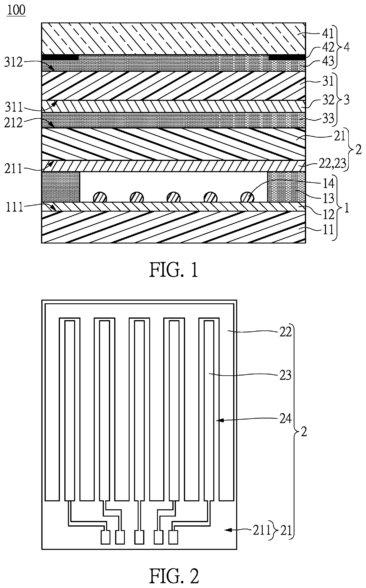
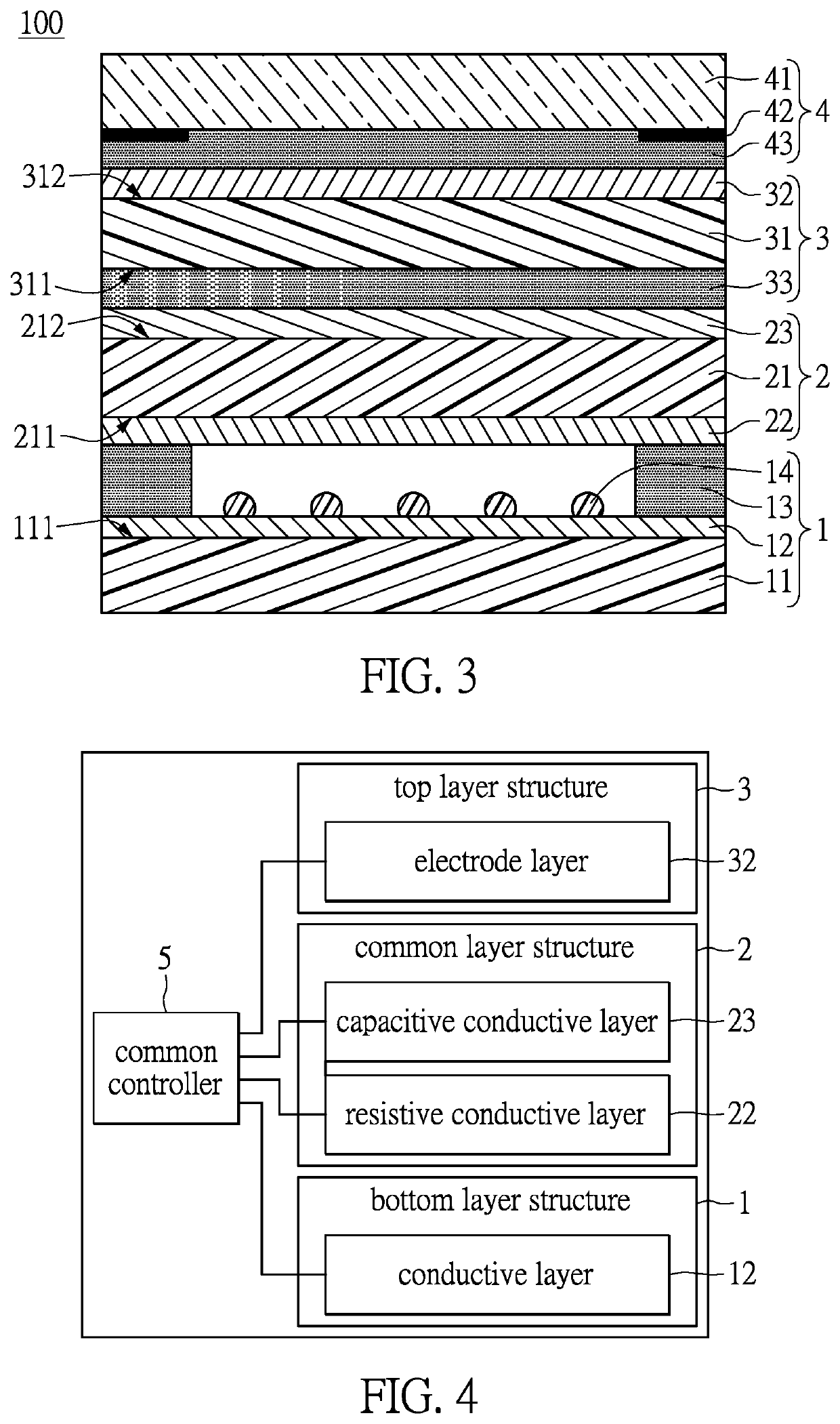
Referring to FIG. 1, FIG. 2, and FIG. 4, which are a first embodiment of the present disclosure. The present embodiment discloses a hybrid touch module 100 capable of providing a resistive touch function and a capacitive touch function, and the hybrid touch module 100 can be applied to electronic products such as smart phones, tablet computers, notebook computers, or industrial computers. The hybrid touch module 100 includes a bottom layer structure 1, a common layer structure 2 disposed on the bottom layer structure 1, a top layer structure 3 attached to the common layer structure 2, and a protection structure 4 attached to the top layer structure 3. In addition, the hybrid touch module 100 further includes a common controller 5 electrically connected to the bottom layer structure 1, the common layer structure 2, and the top layer structure 3 (as shown in FIG. 4). The specific structures of each component of the hybrid touch module 100 in the present embodiment will be individually...

second embodiment

Referring to FIG. 3, which is a second embodiment of the present disclosure. The present embodiment discloses a hybrid touch module 100 including a bottom layer structure 1, a common layer structure 2, a top layer structure 3, a protection structure 4, and a common controller 5. The structural design and the positional arrangement of the bottom layer structure 1, the protection structure 4, and the common controller 5 of the present embodiment are substantially the same as described in the first embodiment. The difference of the present embodiment compared to the first embodiment is the structural design and the positional arrangement of the common layer structure 2 and the top layer structure 3.

As described in more detail below, in the present embodiment, the capacitive conductive layer 23 of the common layer structure 2 is disposed on the second surface 212 of the common film 21, and the electrode layer 32 of the top layer structure 3 is disposed on the top face 312 of the insulat...

third embodiment

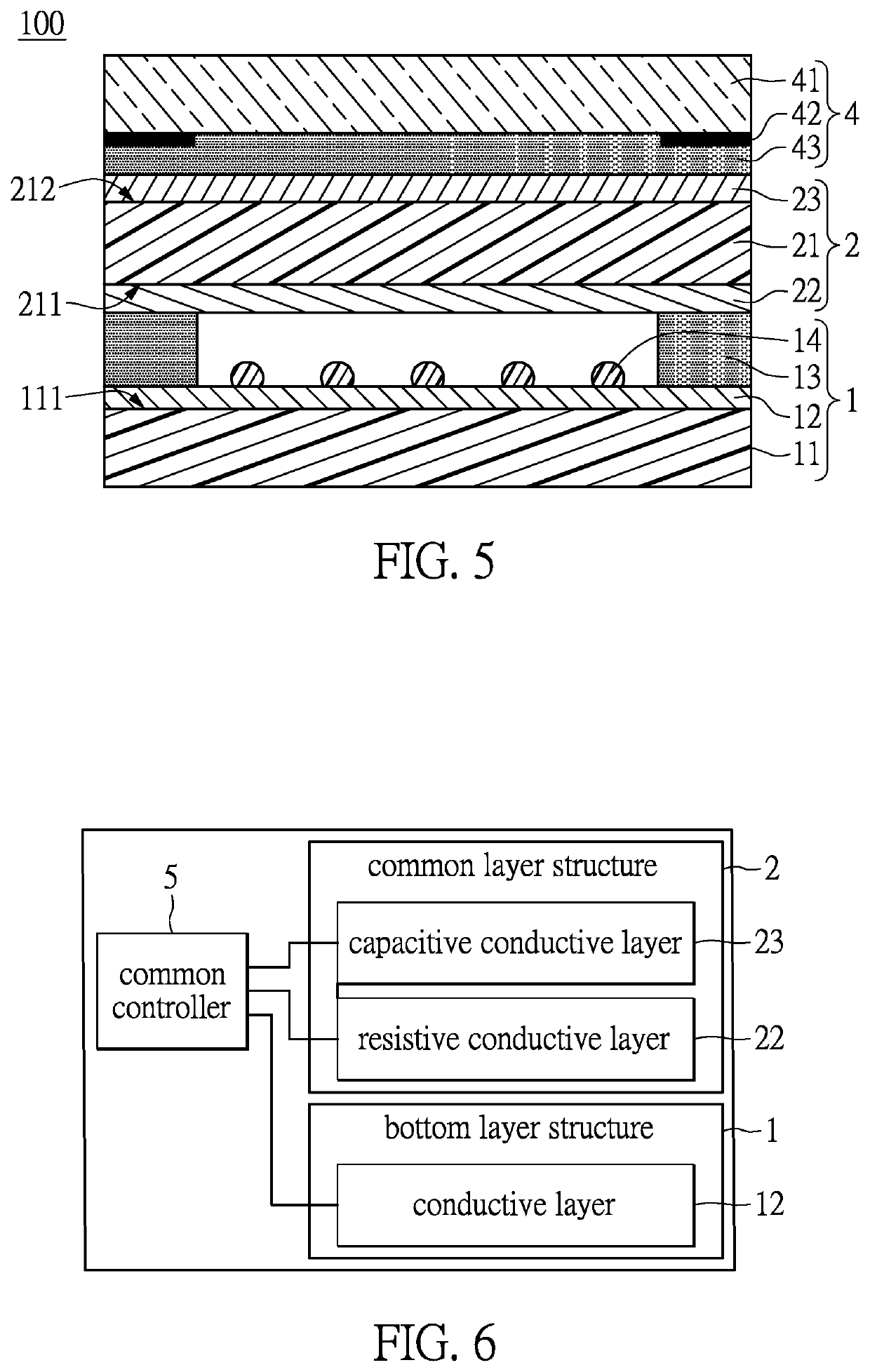
Referring to FIG. 5 and FIG. 6, which are a third embodiment of the present disclosure. The present embodiment discloses a hybrid touch module 100 including a bottom layer structure 1, a common layer structure 2, a protection structure 4, and a common controller 5. The structural design of each component of the present embodiment is substantially the same as described in the second embodiment. The difference of the present embodiment compared to the second embodiment is that the hybrid touch module 100 of the present embodiment does not include the top layer structure 3.

As described in more detail below, since the hybrid touch module 100 of the present embodiment does not include the top layer structure 3, the hybrid touch module 100 provides a capacitive touch function via the capacitive conductive layer 23 and the common film 21 of the common layer structure 2. That is, the common layer structure 2 is capable of independently providing the capacitive touch function without being c...


PUM

PropertyMeasurementUnit
conductiveaaaaaaaaaa
resistive conductiveaaaaaaaaaa
capacitive conductiveaaaaaaaaaa

Abstract

A hybrid touch module includes a bottom layer structure, a common layer structure, and a top layer structure. The bottom layer structure includes a conductive layer, and a bezel disposed on the conductive layer. The common layer structure is disposed on the bezel. The common layer structure includes a common film, a resistive conductive layer, and a capacitive conductive layer. The resistive conductive layer and the capacitive conductive layer are disposed on a first surface of the common film. The top layer structure is attached to the common layer structure, and the top layer structure includes an insulation film and an electrode layer disposed on the insulation film. The common layer structure can be cooperated with the bottom layer structure to provide a resistive touch function, and the common layer structure can be cooperated with the top layer structure to provide a capacitive touch function.

Description

BACKGROUND OF THE INVENTION1. Field of the InventionThe present disclosure relates to a touch module, and in particular, to a hybrid touch module having a resistive touch function and a capacitive touch function.2. Description of Related ArtConventional touch module is classified into a resistive touch module and a capacitive touch module. The resistive touch module performs a touch operation by pressing, which has less restrictions on operating conditions, but is inferior to the capacitive touch module in smoothness of the touch operation (especially for users who often need to write and draw). The capacitive touch module is better in smoothness of the touch operation, but has more restrictions on operating conditions (i.e. the user can not wear gloves when performing the touch operation). In addition, both the resistive touch module and the capacitive touch module have the drawbacks that the user may make a touch error easily when touching the touch module.In addition, if the resi...

Claims


Application Information

Patent Timeline
Patent Type & Authority Patents(United States)
IPC IPC(8): G06F3/044G06F3/041G06F3/045
CPCG06F3/0416G06F3/044G06F3/045G06F2203/04106
Inventor TSAI, HUNG-YUTSAI, CHANG-YOU
Owner HIGGSTEC
Why Eureka
Try Eureka