Oil transfer assembly, to let lubricating oil flow from a stationary part to a rotating part, in particular for an epicyclic transmission

a technology of oil transfer and rotating parts, which is applied in the direction of gear lubrication/cooling, adjustment joints, pipe joints, etc., can solve the problems of insufficient oil transfer systems described above, inconsiderable risk of damage to seals, correct, etc., and achieves the effect of simple and affordabl

Active Publication Date: 2020-03-03
GE AVIO
View PDF31 Cites 0 Cited by
  • Summary
  • Abstract
  • Description
  • Claims
  • Application Information

AI Technical Summary

Benefits of technology

[0008]It is the object of the present invention to provide an oil transfer assembly, to let lubricating oil flow from a stationary part to a rotating part, in particular for an epicyclic transmission, which allows the above problems to be solved in a simple and affordable manner.

Problems solved by technology

In these cases, the problem occurs of transferring the lubricating oil in an efficient and reliable manner from a stationary part (typically an oil reservoir) to a rotating part, that is the planet-carrier and the components supported thereby.
The known oil transfer systems described above are not satisfactory due to the elevated accuracy required in processing and mounting the components which define the aforesaid radial clearance.
Furthermore, during assembly there is a non inconsiderable risk of damaging the seals when the sleeve is axially inserted, whereby the correct. sealing is compromised.
Furthermore, the known oil transfer system described above is not able to compensate for the wear and inevitable variations of relative position between the stationary part and the rotating part (caused for example by differences in temperature between the startup conditions and the running conditions).
Furthermore, in current epicyclic transmissions for vehicles, the pressure and flow rate values required for the lubrication and the peripheral speed values of the planet-carrier are relatively high and therefore may compromise the desired sealing, especially when the components are worn.

Method used


Image

  • Oil transfer assembly, to let lubricating oil flow from a stationary part to a rotating part, in particular for an epicyclic transmission
  • Oil transfer assembly, to let lubricating oil flow from a stationary part to a rotating part, in particular for an epicyclic transmission
  • Oil transfer assembly, to let lubricating oil flow from a stationary part to a rotating part, in particular for an epicyclic transmission

Examples


Embodiment Construction

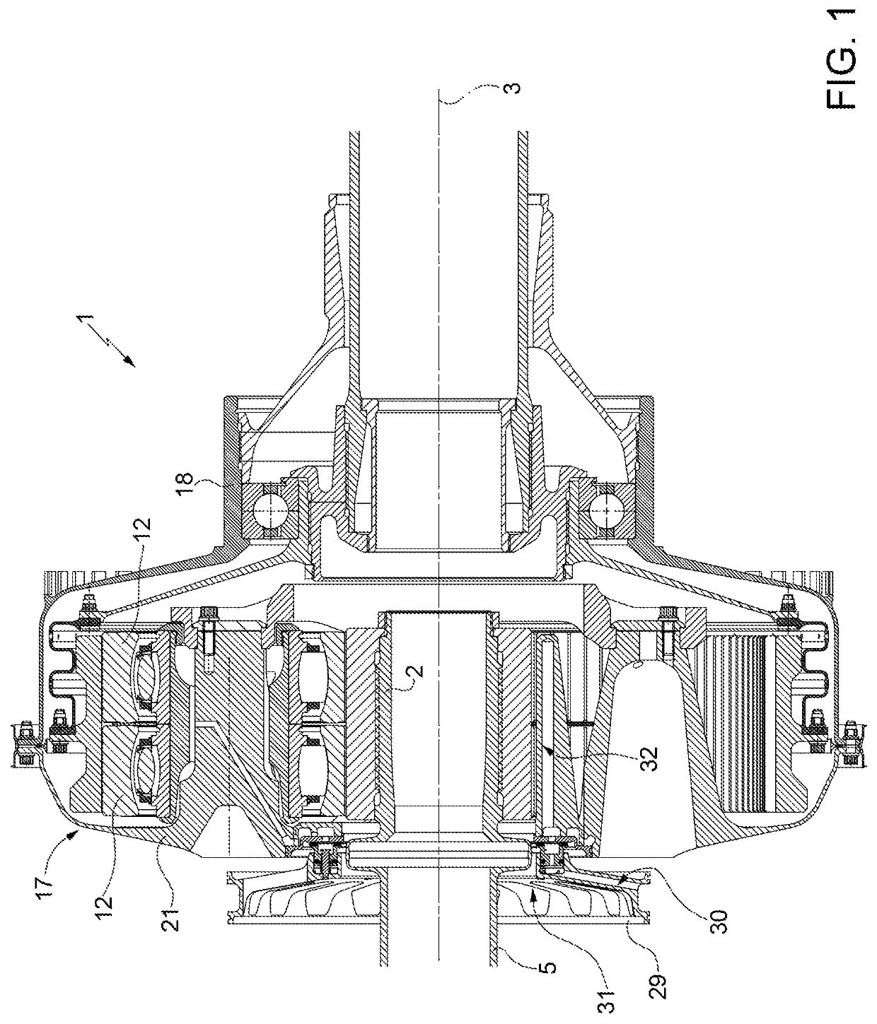
[0016]With reference to FIG. 1, numeral 1 indicates an epicyclic transmission, in particular for aeronautic applications, comprising a pinion 2, which is rotary about an axis 3 and is connected to a transmission shaft 5 in an angularly fixed manner.

[0017]Gearing 1 also comprises a plurality of planet wheels 12, supported, in a manner not described in detail, by planet-carrier 17, which is rotating about axis 3 and, preferably, is connected to a transmission member 18 in an angularly fixed manner.

[0018]The planet-carrier 17 is defined by a structure comprising an annular portion 21, which is coaxial to shaft 5, has a substantially plate-like shape, axially faces the planet wheels 12 and is spaced from shaft 5 and from pinion 2.

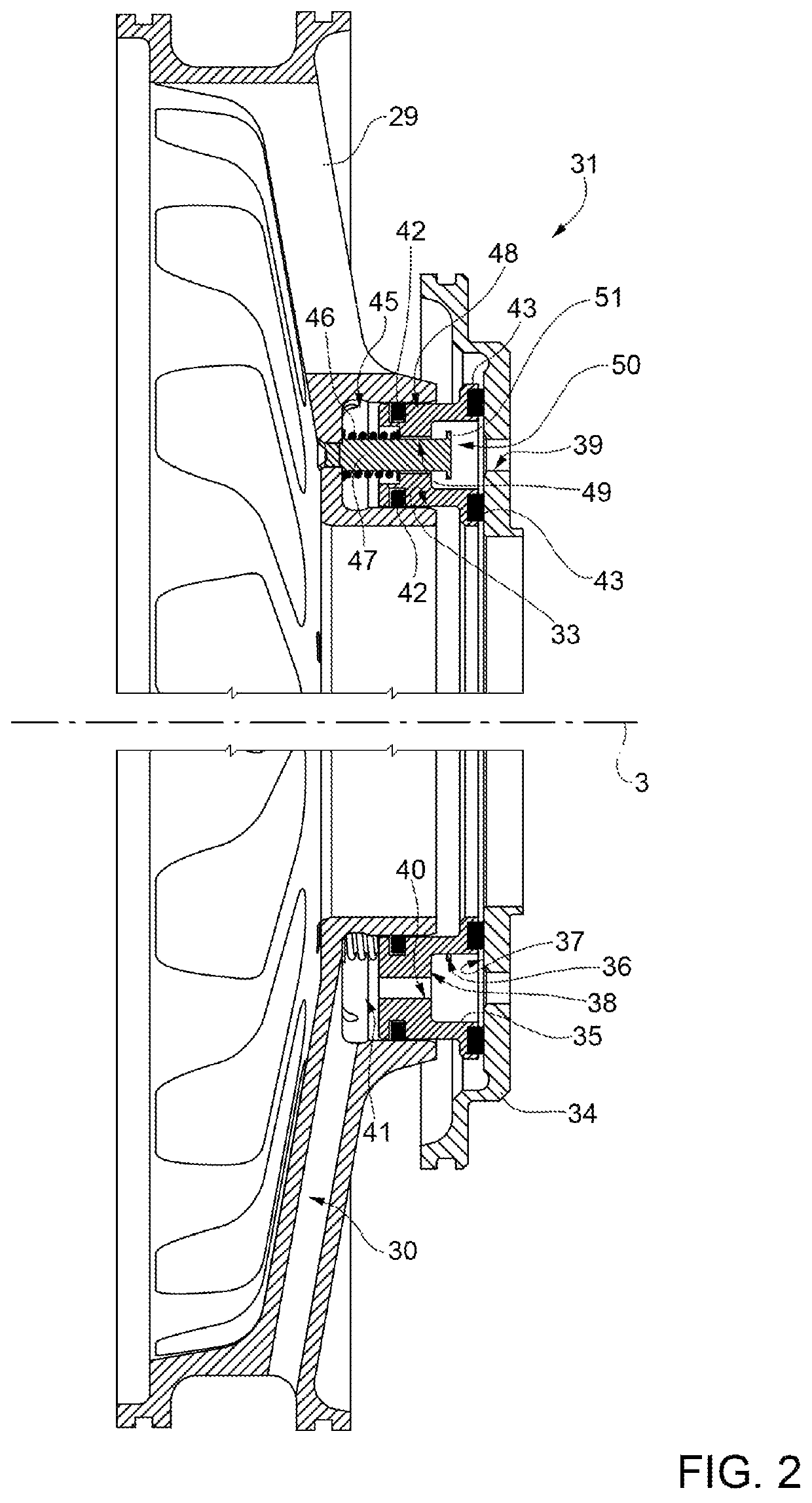
[0019]The planet-carrier 17 axially faces a structure 29 which is fixed and has one or more channels 30 defining an inlet for receiving lubricating oil which is pressurized from a reservoir (not illustrated) by one or more pumps (not illustrated). In particular...


PUM


Abstract

An oil transfer assembly has a fixed structure, with at least one inlet for receiving lubricating oil, and an interface member rotating about an axis and having a front face, from which at least one duct starts for conveying the lubricating oil; the assembly is provided with a slide having an annular chamber, which is delimited axially, on one side, by the front face and connects the inlet with the duct; the slide is coupled to the front face so as to guarantee a seal for the fluid of the annular chamber and engages a guide seat provided in the structure in an axially sliding manner.

Description

TECHNICAL FIELD[0001]The present invention relates to an oil transfer assembly, to let lubricating oil flow from a stationary part to a rotating part, in particular for an epicyclic transmission.BACKGROUND ART[0002]As is known, an epicyclic transmission comprises a pinion, a ring gear and a plurality of toothed planet wheels, which are interposed between the pinion and the ring gear and are supported by a planet-carrier. A transmission of such a type is capable of transmitting the motion between coaxial shafts rotating at different speeds and is very effective in providing such a function while maintaining contained weight and volumes. Epicyclic transmissions are largely used also in aeronautic engines, for example to transmit the motion to the fan in turbofan engines.[0003]In most applications, the planet-carrier is of stationary type and is coupled to the fixed structure of the engine by means of a flexible element. Under these conditions, the components supported by the planet-ca...

Claims


Application Information

Patent Timeline
Patent Type & Authority Patents(United States)
IPC IPC(8): F16H57/04F16L27/08
CPCF16H57/0423F16H57/043F16H57/0486F16L27/0812F16H57/0479F16L27/082F16H57/042F16H57/0426
Inventor ALTAMURA, PAOLO
Owner GE AVIO
Why Eureka
Try Eureka