Optical interrogation and control of dynamic biological functions

a dynamic biological function and optical interrogation technology, applied in the field of optical interrogation and control of dynamic biological functions, can solve the problems of high-sensitivity photodetectors and special focusing optics, system is not easily miniaturized, and high-throughput applications and incubators are not easy to miniaturize, etc., to achieve ultra-high spatiotemporal resolution, easy combinability, and simple and affordable

Inactive Publication Date: 2017-12-07
OXFORD UNIV INNOVATION LTD +1
View PDF0 Cites 2 Cited by
  • Summary
  • Abstract
  • Description
  • Claims
  • Application Information

AI Technical Summary

Benefits of technology

[0013]The processing means may be arranged to analyze the image data to determine one or more parameters of the image data, or one or more parameters of the biological system. The parameters may comprise the presence or absence of wavefronts if the biological system comprises cardiac tissue or cells, or they may include the speed, or direction, or frequency of the wavefronts, or a measure of the shape of the wavefronts, such as radius of curvature. The processing means may be arranged to compare one or more of these parameters with one or more reference values to determine whether the biological system meets one or more criteria, and may generate an output on the basis of that determination. Real-time feedback control may be achieved as the imaging output is compared to desired reference values and the stimulation pattern is applied to bring or maintain the biological system closer to the set target, including but not limited to prevention of arrhythmia events. For high-throughput systems, this enables the system to test large numbers of biological systems and record the results for analysis.
[0018]The system may be a transmitted-light optical imaging system. Some embodiments of the invention can: 1) be extremely simple and affordable, not requiring special optics and light sources, lens-free or using low-NA lenses and coherent, partially coherent, or non-coherent light sources; 2) be completely non-invasive, non-toxic, dye free imaging, allowing for repeated monitoring over days; 3) be spectrally flexible (wavelength-independent), hence easily combinable with various optogenetic actuators for truly simultaneous imaging; 4) provide fast wide-field (non-scanning) imaging, suitable for tracking intricate fast excitation waves; 5) provide ultra-high spatiotemporal resolution, revealing subcellular events at centimeter field of view; 6) enable monitoring of multiple preparations and samples simultaneously in a very time efficient manner.
[0019]The system may not require focusing (moving the preparation to a particular position on the optical axis). This omission of focusing optics may allow for straightforward miniaturization and is a significant departure from conventional imaging systems which would have to focus on different preparations individually prior to data capture. The spectral flexibility of the imaging method (practically any wavelength can be used to illuminate, unlike standard fluorescent imaging), can allow for easy combination with optogenetic stimulation, and this can allow for real time, all-optical, stimulation and monitoring of biological systems.
[0031]The processing means may be arranged to control the optical stimulation means, and to vary its optical output in response to the analysis of the image data. The processing means may be arranged to vary said optical output while the imaging system is imaging the biological system. The system may thereby provide real-time control of activity of the biological system.
[0034]High-throughput drug screening—since it can offer massive parallelization at low cost and with new functionality (the ability to stimulate and image optically at millions of locations);

Problems solved by technology

This has many limitations, including: 1) the imaging is terminal when fluorescent dye labelling is applied due to phototoxicity, thus precluding long-term monitoring; 2) prior genetic modification is required when genetically-encoded dyes are used; 3) most current dye indicators / sensors require expensive high-sensitivity photodetectors and special focusing optics; and 4) such systems are not amenable to miniaturization, high-throughput applications and incubator long-term use.
As implemented, 1) this system is not easily miniaturizable; 2) it is not easily combinable with optogenetic means of actuation (due to the white light used); 3) it worked strictly in trans-illumination regime (the illuminator and the photodetector were on opposite sides of the sample); 4) it was not possible to observe propagation of waves directly (without processing); and 5) the spatial resolution was unclear.

Method used


Image

  • Optical interrogation and control of dynamic biological functions
  • Optical interrogation and control of dynamic biological functions
  • Optical interrogation and control of dynamic biological functions

Examples


second embodiment

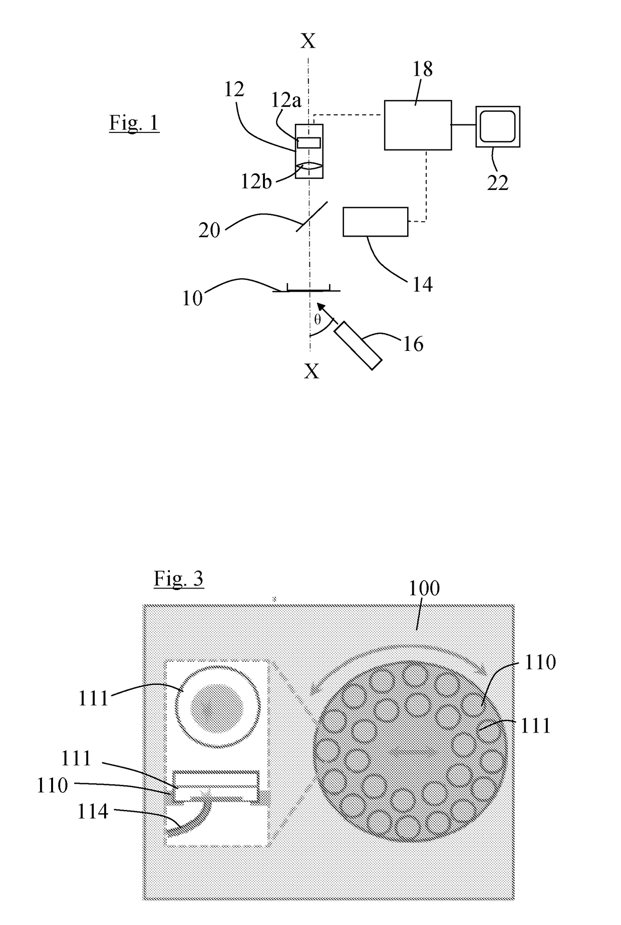
[0065]The control system 18 is also connected to the camera 12 and is arranged to receive and process detector signals from the detector array 12a of the camera and to generate image data from the signals. It is further arranged to process the image data using image processing algorithms to improve the image data. The control system 18 is also connected to a display 22 and arranged to use the image data to control the display 22 to display images of the sample. The images may be real time video images. The control system may be arranged to analyse the image data, for example as described below with reference to the

[0066]It has been found that if multicellular preparations of optogenetically modified cardiomyocytes, produced for example using channelrhodopsins, are placed on the sample holder 10, and stimulated with light, for example at a point or line, or series of points or lines, the activation wavefronts that travel through the sample can be seen in real time in the images with ...

third embodiment

[0080]Referring to FIGS. 4 and 5, in the invention, a group of four camera devices 212, which in this case are mobile phones with cameras, are arranged over a standard 96 well plate 210, so that each camera device 212 images a respective group of 24 of the wells 211 each of which holds a respective sample. Two illuminating light sources 216, which again can be LEDs or laser diodes, are arranged to direct illuminating light simultaneously at the undersides of all of the wells 211. A further LED light source 214, of a different wavelength from the illuminating light source, is provided for optogenetic stimulation of samples located in the wells 211. These may be preparations with opsins. In this embodiment the stimulating LED 214 provides uniform illumination to stimulate all samples in the wells 211. The camera devices 212 are each connected to a central control unit 218, which may be in the form of a suitably programmed PC, and the illuminating light sources 216 and stimulating ligh...


PUM

PropertyMeasurementUnit
FWHMaaaaaaaaaa
FWHMaaaaaaaaaa
FWHMaaaaaaaaaa

Abstract

An imaging system for imaging live biological systems comprises a detector array (12a) having an optical axis (X-X) and arranged to detect light and output detector signals, a support (10) arranged so support a biological system on the optical axis, an illuminating light source (16) located off the optical axis and arranged to direct at least partially-coherent light towards the biological system, and processing means (18) arranged to receive the detector signals and generate image data.

Description

[0001]This invention was made with US government support under grant number HL111649 awarded by the National Institute of Health. The US government has certain rights in the invention.FIELD OF THE INVENTION[0002]The present invention relates to methods, apparatus and software for optical imaging of dynamic processes in live biological systems, and to optical interrogation and imaging of such systems.BACKGROUND TO THE INVENTION[0003]Researchers have been using in vitro multicellular preparations of cardiac myocytes for over 40 years to study critical tissue-level properties of the heart. In the last 15 years, these have included monolayers of cultured cardiomyocytes, derived from the native heart or differentiated from stem cells, e.g. embryonic stem cells (ESC), induced pluripotent stem cells (iPSC). When imaged at macroscopic space scales (mm and cm scales), such multicellular preparations have allowed the investigation of complex dynamic phenomena, such as wave propagation and pat...

Claims


Application Information

Patent Timeline
Patent Type & Authority Applications(United States)
IPC IPC(8): G01N33/483G01N21/63G06T7/00
CPCG01N33/4833G01N21/63G06T7/0012G01N2333/705G06T2207/10152G06T2207/10056G06T2207/30024G06T2207/30048G01N2201/062C12M41/36C12M31/02
Inventor ENTCHEVA, EMILIABUB, GIL
Owner OXFORD UNIV INNOVATION LTD
Why Eureka
Try Eureka