
Fin and heat exchanger having same

a heat exchanger and fin technology, applied in the field of heat exchangers, can solve the problems of reducing the effective heat exchange area, affecting the stability of temperature, and difficulty in discharge of condensing water, and achieves the effects of improving heat exchange performance of heat exchangers, low frosting speed, and high discharging speed of condensing water

Active Publication Date: 2020-03-03
SANHUA(HANGZHOU) MICRO CHANNEL HEAT EXCHANGER CO LTD
View PDF28 Cites 1 Cited by
  • Summary
  • Abstract
  • Description
  • Claims
  • Application Information

AI Technical Summary

Benefits of technology

The fin design enhances heat exchange efficiency and system stability by accelerating condensing water discharge and slowing frosting, thereby improving the overall performance of the heat exchanger.

Problems solved by technology

The frosting at the surface of the fin reduces an effective heat exchange area of the heat exchanger, and systems such as an air conditioner applying the heat exchanger enter a defrost process frequently, influencing stability of the temperature.
The condensing water at the surface of the fin flows downward and is discharged relying on an action of gravity, however, as a flowing path of the condensing water is longer, it is difficult to discharge the condensing water, which increases the heat exchange resistance of the heat exchanger and influences the heat exchange capacity of the heat exchanger.

Method used


Image

  • Fin and heat exchanger having same
  • Fin and heat exchanger having same
  • Fin and heat exchanger having same

Examples


Embodiment Construction

[0038]Embodiments of the present disclosure are described in detail in the following. The examples of the embodiments are illustrated in the drawings. The same or similar elements and the elements having same or similar functions are denoted by like reference numerals throughout the descriptions. The embodiments described herein with reference to drawings are explanatory, illustrative, and used to generally understand the present disclosure and cannot be construed to limit the present disclosure.

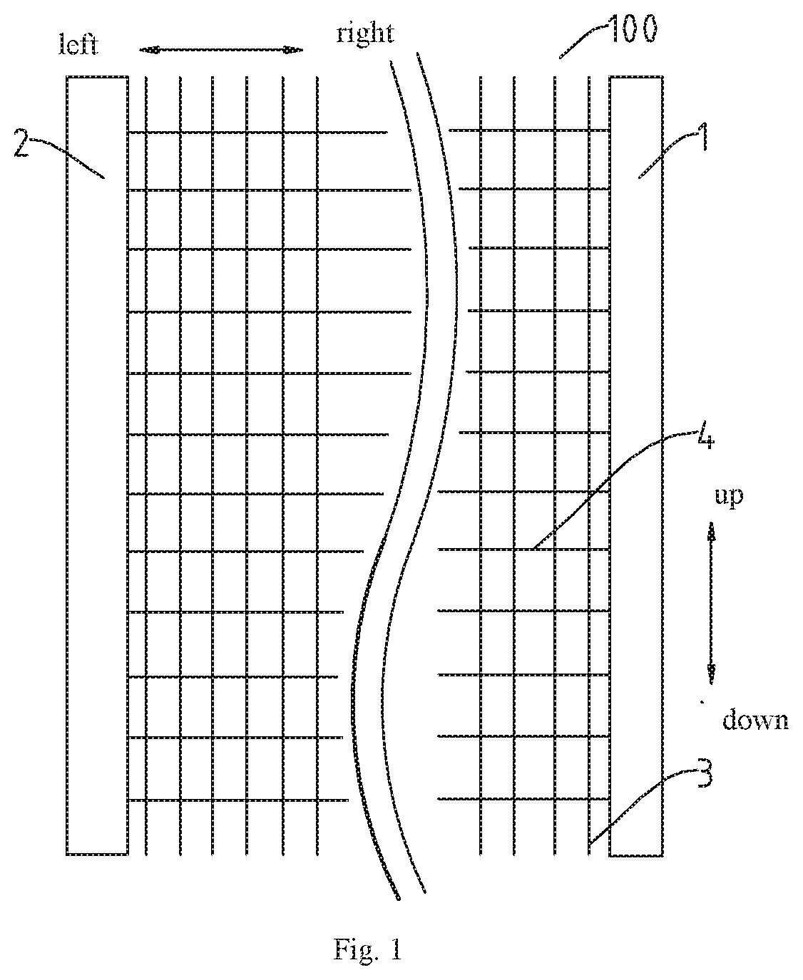
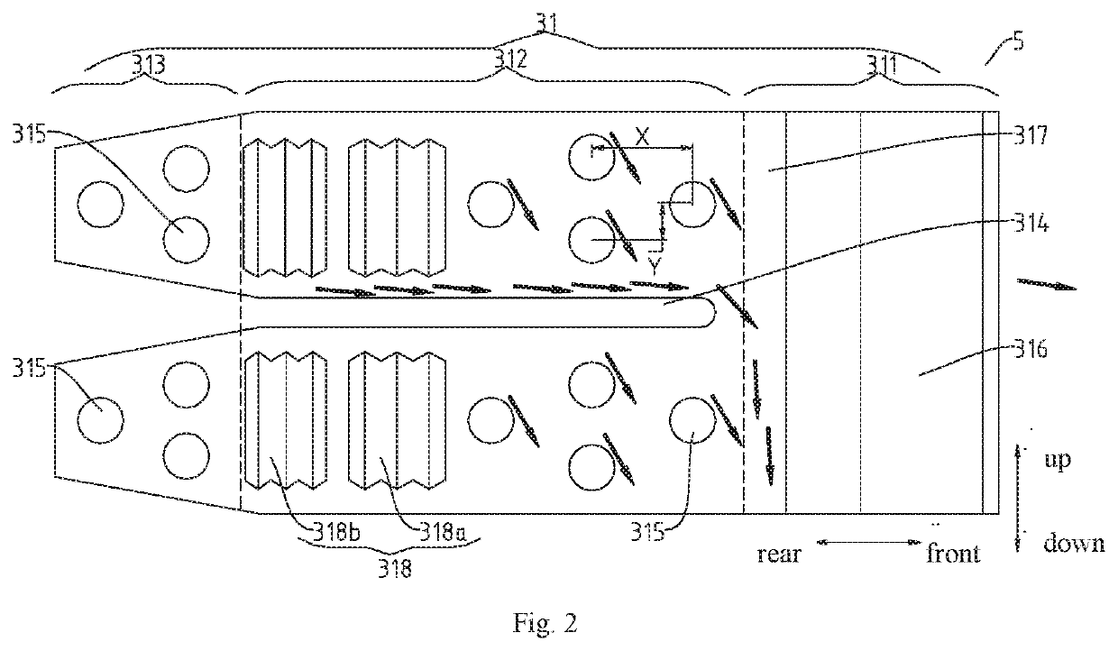
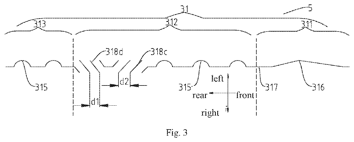
[0039]A fin 3 according to embodiments of the first aspect of the present disclosure will be described with reference to FIG. 1 to FIG. 9 in the following. The fin 3 is adapted to a micro-channel heat exchanger, which has advantages such as a high discharging speed of condensing water and a slow frosting speed, so that the heat exchange performance of the heat exchanger can be improved.

[0040]As illustrated in FIG. 1 to FIG. 9, the fin 3 according to embodiments of the present disclosure incl...


PUM


Abstract

A fin and a heat exchanger having the fin, wherein the fin includes a sheet body. The sheet body includes a plurality of cooling sheet units arranged along a longitudinal direction of the sheet body. Each cooling sheet unit includes a windward zone, a main heat exchange zone and a leeward zone arranged along a transverse direction of the sheet body. The windward zones of adjacent cooling sheet units are connected to each other. A flat tube groove extends between the leeward zone and the main heat exchange zone of one of the adjacent cooling sheet units and the leeward zone and the main heat exchange zone of the other of the adjacent cooling sheet units. Each cooling sheet unit is provided with a plurality of protrusions spaced apart from each other.

Description

CROSS-REFERENCE TO RELATED APPLICATIONS[0001]The present application is a national phase entry under 35 USC § 371 of PCT International Patent Application No. PCT / CN2016 / 099628 filed on Sep. 21, 2016, which claims priority to and all the benefits of Chinese Patent Application No. 201510602848.6 filed on Sep. 21, 2015, the entire disclosures of which are incorporated herein by reference.BACKGROUND OF THE INVENTION1. Field of the Invention[0002]The present disclosure relates to a technical field of heat exchangers, and more particularly to a fin and a heat exchanger having the fin.2. Description of the Related Art[0003]The micro-channel heat exchanger in the related art consists of a header pipe, a flat tube and a fin. The fin is disposed between adjacent flat tubes, a surface of the fin is provided with a shutter occupying the vast majority of the fin, a windward end of the fin has a higher heat exchange intensity, which causes more condensing water or frosting amount at the windward ...

Claims


Application Information

Patent Timeline
Patent Type & Authority Patents(United States)
IPC IPC(8): F28F1/32F28F1/30
CPCF28F1/325F28F1/30F28F1/32F28F2215/08F28F2215/12
Inventor WANG, LEILEIHE, YANLIANG, XIN
Owner SANHUA(HANGZHOU) MICRO CHANNEL HEAT EXCHANGER CO LTD
Learn More