Method of controlling water injector for preventing damage to catalyst for exhaust gas purification and engine driven by method

a technology of exhaust gas purification and water injector, which is applied in the direction of electrical control, machines/engines, electric control of exhaust gas treatment, etc., can solve the problems of degrading engine combustion characteristics, time taken for water to be evaporated, and much greater turbo lag range than that of natural inhalation engines, so as to reduce the scavenging region

Active Publication Date: 2020-03-10
HYUNDAI KEFICO CORP
View PDF17 Cites 1 Cited by
  • Summary
  • Abstract
  • Description
  • Claims
  • Application Information

AI Technical Summary

Benefits of technology

[0011]An object of the present invention is to provide a method of controlling a water injector, which can prevent damage to a catalyst for exhaust gas purification attributable to a temperature rise, and an engine driven by the method.
[0014]In an embodiment of the present invention, when the state of the catalyst is determined to be a normal state in the catalyst state determination step, the existing driving of the water injector may be maintained.
[0021]Furthermore, the present invention may provide an engine including a water injector for injecting water into the combustion chamber of an engine to which a turbo system has been applied. The engine according to an aspect of the present invention may have a configuration, including a catalyst temperature modeling calculation unit configured to calculate a temperature of a catalyst for exhaust gas purification through modeling and to transmit the calculated temperature to a controller, an exhaust gas temperature sensor configured to detect a temperature of exhaust gas discharged through the exhaust valve of the engine and to transmit the detected temperature to the controller, and the controller configured to calculate a water injection flow value at which the temperature of the catalyst may drop to a preset temperature when data values detected by the catalyst temperature modeling calculation unit and the exhaust gas temperature sensor exceed a preset range and to control the water injection operation of the water injector based on the calculated water injection flow value.
[0023]In an embodiment of the present invention, the controller may calculate a required cooling rate necessary to lower the temperature of the catalyst for exhaust gas purification, may calculate an actual cooling rate of the catalyst based on the adopted water injection flow value, and may adjust fuel density of supply air corresponding to a zero fuel efficiency target value when the actual cooling rate is smaller than the required cooling rate.
[0026]In an embodiment of the present invention, the controller may reduce the scavenging region when the temperature of the catalyst rises even after the waterjet operation of the water injector is performed.

Problems solved by technology

However, the engine to which the turbo system has been applied has a problem in that the range of the turbo lag is much greater than that of the natural inhalation engine.
In the conventional technology, however, when the amount of water injection jet by a water injector is excessively high, a lot of time is taken for the water to be evaporated because all the water is not evaporated within a combustion period, thereby degrading engine combustion characteristics and resulting in an exhaust gas increase.
In this case, damage to a catalyst for exhaust gas purification may occur because oxygen is saturated in the catalyst.
In this case, however, the catalyst may be damaged due to overheating.
Furthermore, there is a problem in that a scavenging region must be reduced in order to prevent the damage.

Method used


Image

  • Method of controlling water injector for preventing damage to catalyst for exhaust gas purification and engine driven by method
  • Method of controlling water injector for preventing damage to catalyst for exhaust gas purification and engine driven by method
  • Method of controlling water injector for preventing damage to catalyst for exhaust gas purification and engine driven by method

Examples


Embodiment Construction

[0033]Hereinafter, embodiments of the present invention are described in detail with reference to the accompanying drawings. Terms or words used in the specification and claims should not be construed as having common or dictionary meanings, but should be construed as having meanings and concepts that comply with the technical spirit of the present invention.

[0034]In the entire specification, when it is described that one member is positioned “on” or “over” the other member, it means that one member may adjoin the other member and a third member may be interposed between the two members. In the entire specification, unless explicitly described to the contrary, the word “include, have, or comprise” will be understood to imply the inclusion of stated elements but not the exclusion of any other elements.

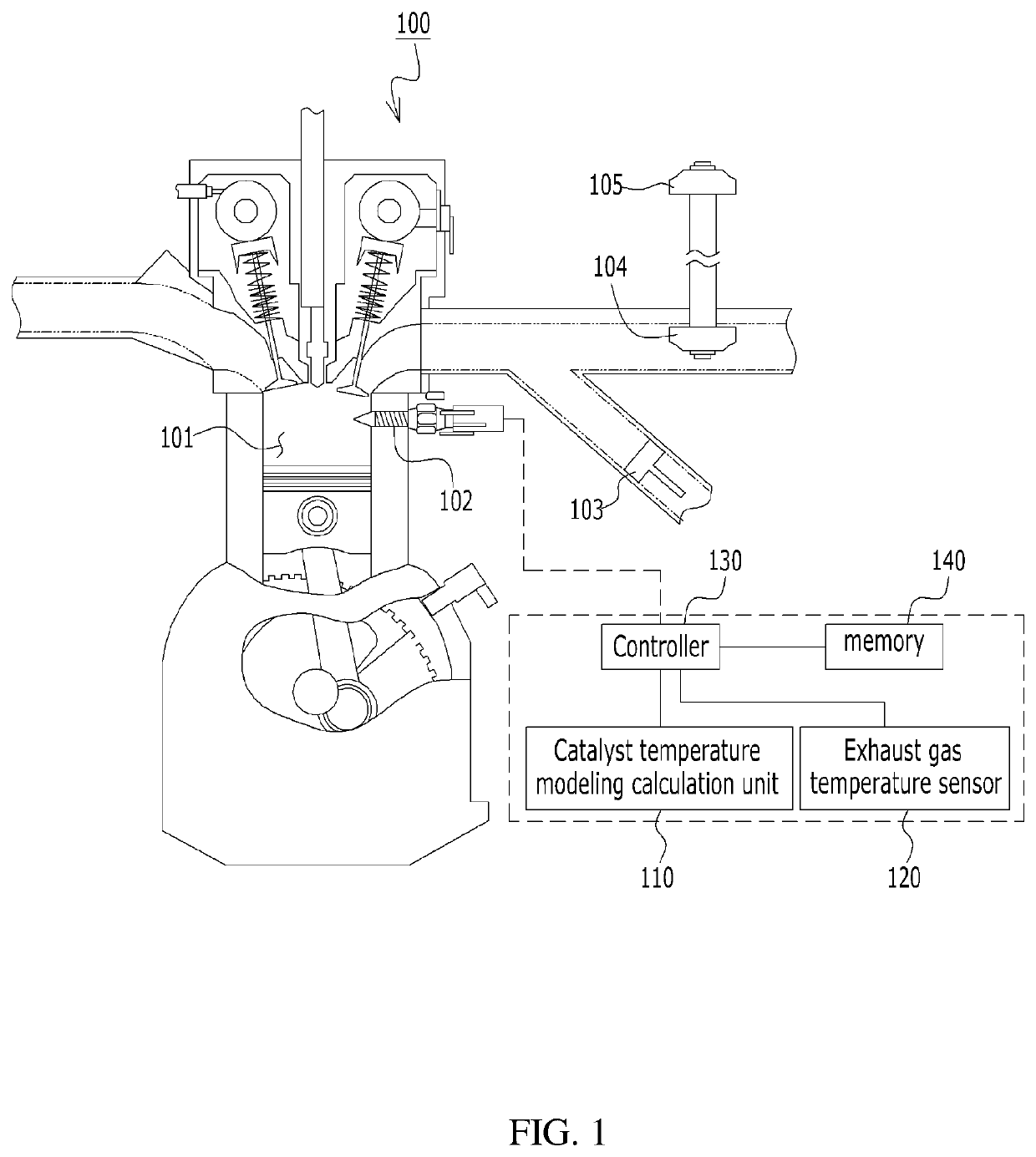
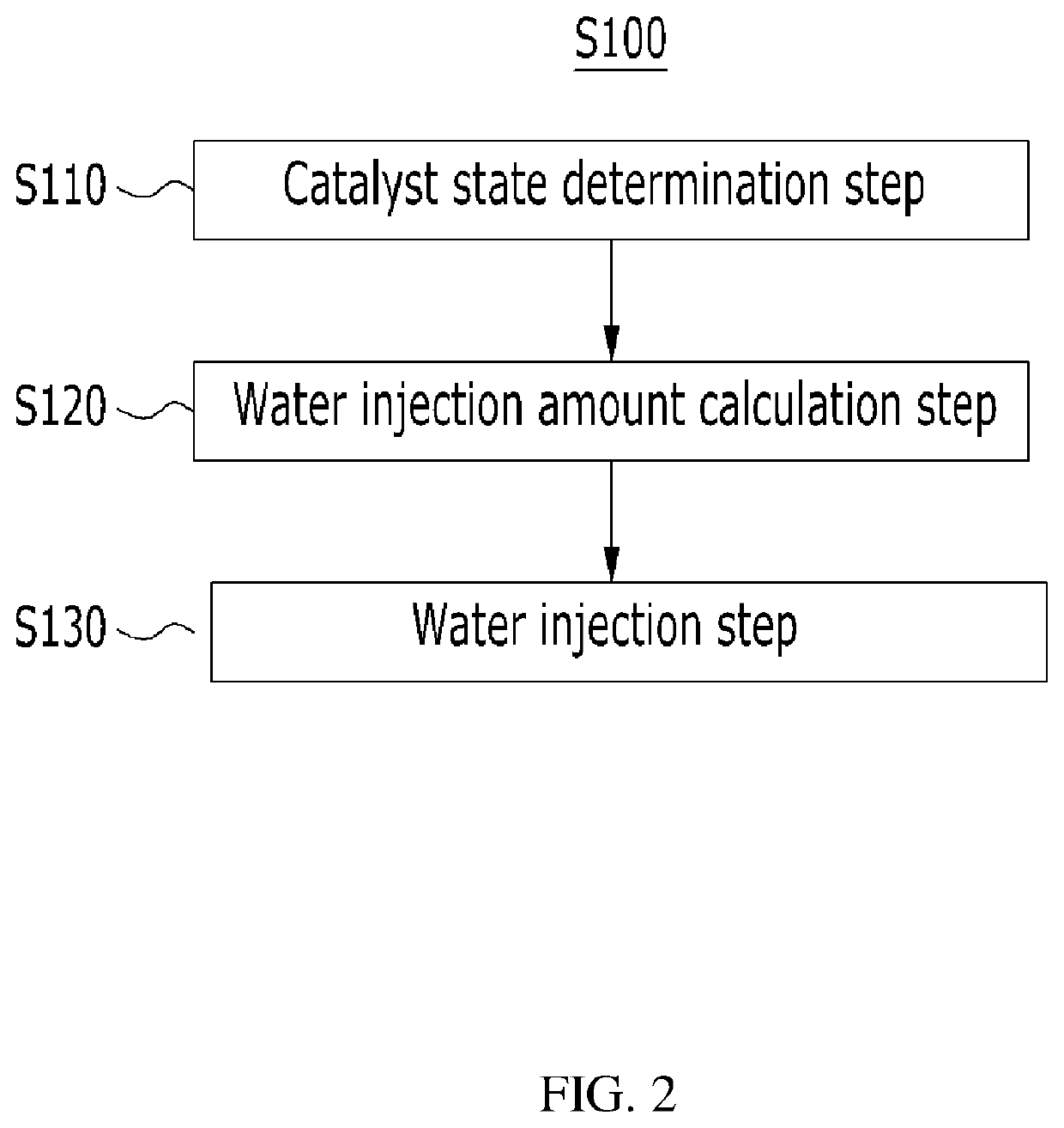
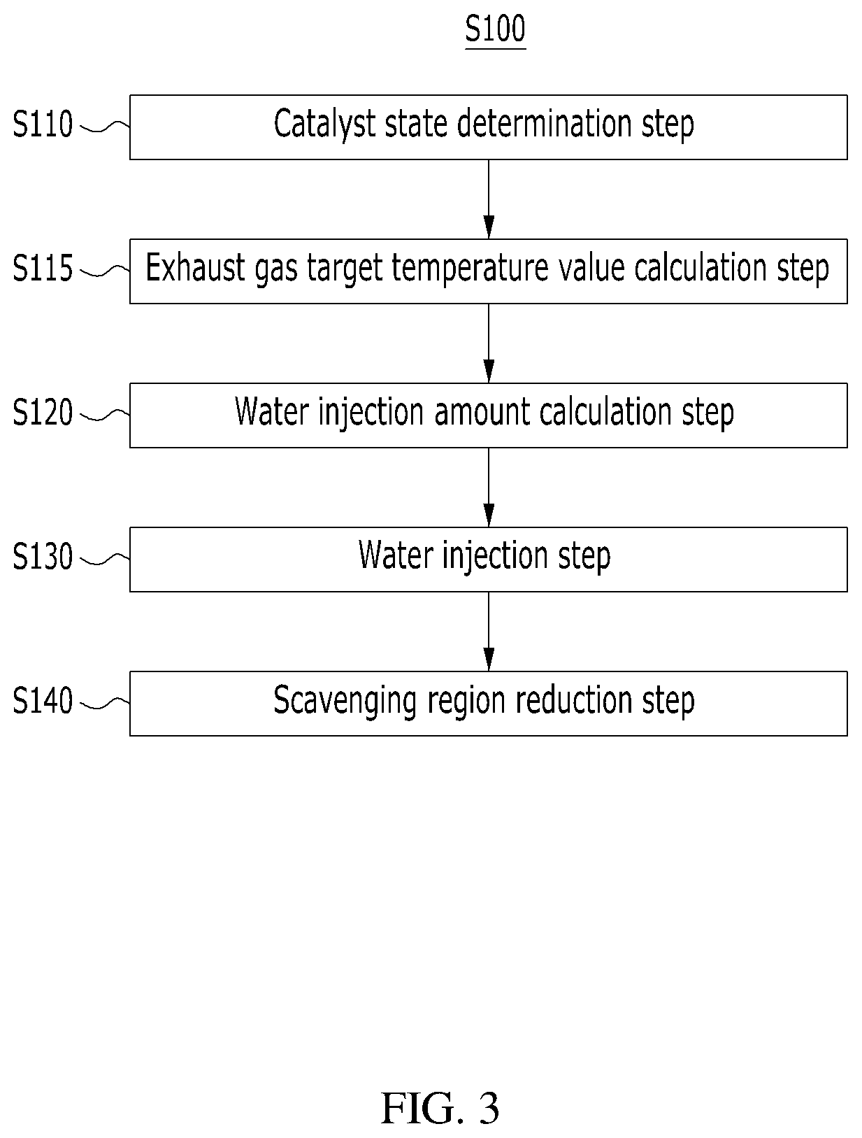
[0035]FIG. 1 shows the configuration of an engine including a water injector according to an embodiment of the present invention. FIG. 2 is a flowchart showing a method of controlling a...


PUM


Abstract

Disclosed are a method of controlling a water injector for preventing damage to a catalyst for exhaust gas purification and an engine driven by the method. A method of controlling the operation of an injector for injecting water into the combustion chamber of an engine to which a turbo system for increasing the amount of air by compressing air has been applied includes a catalyst state determination step of determining the danger condition of a catalyst for exhaust gas purification by detecting the state of the catalyst, a water injection amount calculation step of calculating a water injection flow value F1 at which a temperature of exhaust gas drops to a preset temperature when the catalyst is in the danger condition, and a water injection step of performing the waterjet operation of a water injector based on the water injection flow value calculated in the water injection amount calculation step.

Description

CROSS REFERENCE TO RELATED APPLICATION[0001]The present application claims the benefit of Korean Patent Application No. 10-2017-0172230 filed in the Korean Intellectual Property Office on Dec. 14, 2017, the entire contents of which are incorporated herein by reference.BACKGROUND OF THE INVENTION1. Technical Field[0002]The present invention relates to a method of controlling a water injector and an engine driven by the method and, more particularly, to a method of controlling a water injector, which can prevent damage to a catalyst for exhaust gas purification attributable to a temperature rise and an engine driven by the method.2. Description of the Related Art[0003]An engine to which a turbo system for increasing the amount of air by compressing air has been applied maximizes a scavenging effect by increasing the operation overlap of an inhalation valve and an exhaust valve in order to reduce a turbo lag phenomenon.[0004]The above-described turbo lag refers to responsiveness delay....

Claims


Application Information

Patent Timeline
Patent Type & Authority Patents(United States)
IPC IPC(8): F02M25/022F02M25/03F02D41/02F02D41/00F02B47/02F02D13/02F02D41/14
CPCF02M25/0227F02D41/0007F02D41/0025F02D41/0235F02M25/03F02B47/02F02D41/1446F02D2041/0265F02D13/0261F02D2200/0804F01N3/2046Y02T10/12F01N9/00F02M25/028F01N2900/1602F01N2900/1404
Inventor CHO, HYUNJAEKIM, YONGHAJUN, SANG-YOUL
Owner HYUNDAI KEFICO CORP
Why Eureka
Try Eureka