Vacuum-assisted pelletizer

a technology of vacuum-assisted pelletizers and pelletizers, which is applied in the field of vacuum-assisted pelletizers, can solve the problems of unsatisfactory “fines”, reduce the “yield”, the quality of pelletized products, and reduce the value of pelletized products, so as to improve the separation of pellets and fines, and improve the capture effect of fines

Active Publication Date: 2020-03-17
BAY PLASTICS MACHINERY CO LLC
View PDF15 Cites 0 Cited by
  • Summary
  • Abstract
  • Description
  • Claims
  • Application Information

AI Technical Summary

Benefits of technology

[0004]The present invention addresses the aforementioned problem by providing both improved separation of pellets and fines and improved capture of fines from the chamber.
[0006]By providing the separate collection of pellets and fines, the yield of accurately sized pellets is improved, and the contamination by fines is reduced.
[0008]The divider plate further provides for the separation of pellets and fines, which even further improves uniformly sized pellets (i.e. the yield of the product). When either or both of the chute sections are connected to a vacuum, the divider plate improves the vacuum effect on the pellets leaving the cutter. The divider plate also directs pellets into the first discharge chute.
[0009]As further disclosed in the current embodiment, the pelletizer may include a compressed air inlet that directs compressed air past the cutting rotor and to the mouth of the first discharge chute. The compressed air assists in moving the pellets from the cutter and into the pellet chute section.

Problems solved by technology

Sometimes this happens multiple times. This process is called “double cutting”, and it results in the creation of undesirable “fines”.
Fines reduce the “yield”, the quality, and the value of the pelletized product.

Method used


Image

  • Vacuum-assisted pelletizer
  • Vacuum-assisted pelletizer
  • Vacuum-assisted pelletizer

Examples


Embodiment Construction

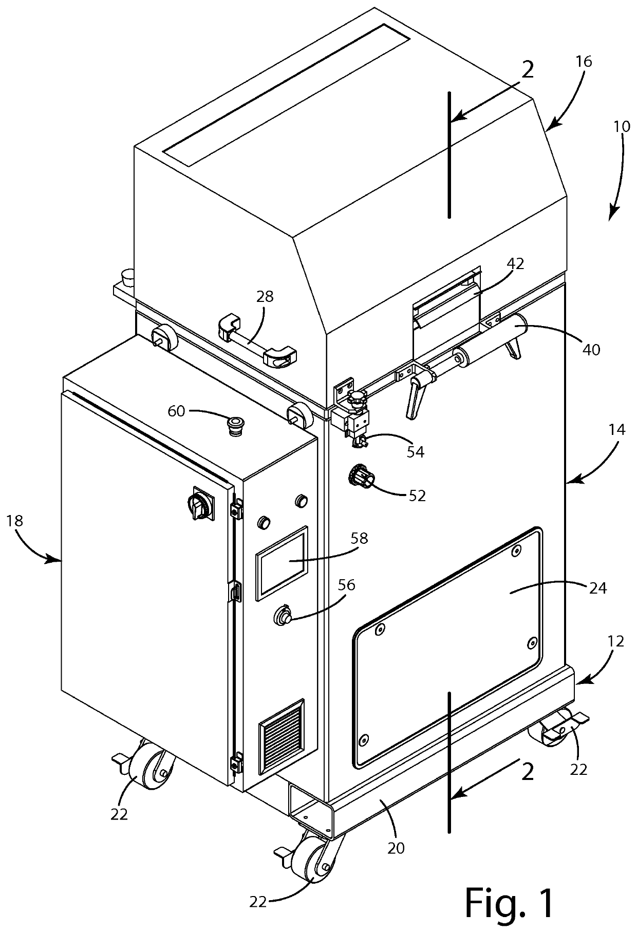
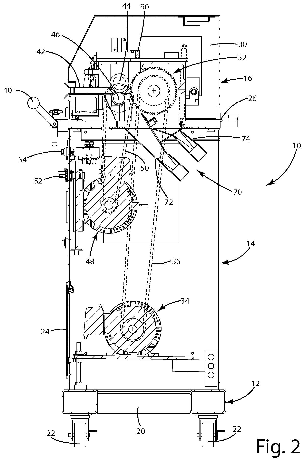
[0017]A pelletizer constructed in accordance with a current embodiment of the invention is illustrated in the drawings and generally designated 10. Referring initially to FIGS. 1-3, the pelletizer 10 includes a base assembly 12, a housing assembly 14, a hood 16, and a control box 18. The housing 14 is supported on the base assembly 12, and the hood 16 and the control box 18 are supported on the housing 14.

[0018]The base assembly 12 is of conventional design and includes a frame 20 supported by a plurality of casters 22. The base assembly 12 supports the remainder of the pelletizer 10.

[0019]The housing 14 is also of conventional design and provides an enclosure for various pelletizer components to be described. The housing 14 includes an access panel 24 providing access to components within the housing.

[0020]The hood 16 is hingedly supported on the housing 14 by way of hinges 26. The hood may be moved between a closed position (illustrated in the drawings) and an open position in whi...


PUM

PropertyMeasurementUnit
plasticaaaaaaaaaa
distanceaaaaaaaaaa
plastic strandaaaaaaaaaa

Abstract

A thermoplastic pelletizer providing enhanced pellet yields with reduced fines contamination. The pelletizer includes a cutting rotor and a feed assembly for feeding plastic to the cutting rotor. The pelletizer further includes two chutes, wherein a first chute arranged to collect pellets, and a second chute arranged to collect fines. A vacuum is drawn on both chutes to assist in the collection of both pellets and fines in their respective chutes. Compressed air is directed past the cutting rotor to the first chute to assist in moving pellets from the cutting rotor to the first chute.

Description

BACKGROUND OF THE INVENTION[0001]The present invention relates to pelletizers for thermoplastics, other plastics, and other materials.[0002]Pelletizers for thermoplastics, other plastics, and other materials are well known to those skilled in the art. Pelletizers typically include a chamber, a rotating cutter within the chamber, a feed mechanism, and a collection chute. The feed mechanism delivers the thermoplastic to the rotating cutter, which cuts the thermoplastic into pellets which are collected in the collection chute. Examples of such technology may be seen, for example, in U.S. Pat. No. 7,124,972 dated Oct. 24, 2006 and U.S. Pat. No. 7,393,201 dated Jul. 1, 2008, both to Fetter.[0003]Pelletizers are designed so that the vast majority of the pellets created by the cutting rotor travel directly into the collection chute. However, some of the pellets will circulate within the cutting chamber to come into contact with the rotating cutter once again. Sometimes this happens multipl...

Claims


Application Information

Patent Timeline
Patent Type & Authority Patents(United States)
IPC IPC(8): B02C23/14B29B9/06B02C23/26B02C18/08B02C23/30B02C18/22B29B9/16
CPCB02C23/26B02C18/2216B02C18/086B02C18/2291B02C23/30B29B9/06B29B9/16
Inventor FETTER, RICHARD H.
Owner BAY PLASTICS MACHINERY CO LLC
Why Eureka
Try Eureka