Method and arrangement of introducing boreholes into a surface of a workpiece mounted in a stationary manner using a boring tool attached to an articulated-arm robot

a technology of introducing boreholes and boring tools, which is applied in the direction of turbines, manufacturing tools, mechanical equipment, etc., can solve the problems of low absolute accuracy of long kinematic chains, low machining speed and machining accuracy, and difficulty in using industrial robots such as such for the purpose of machining workpieces, etc., to achieve the speed with which drilling operations can be carried out, the effect of improving quality and high degree of precision

Active Publication Date: 2020-03-17
FRAUNHOFER GESELLSCHAFT ZUR FOERDERUNG DER ANGEWANDTEN FORSCHUNG EV
View PDF15 Cites 4 Cited by
  • Summary
  • Abstract
  • Description
  • Claims
  • Application Information

AI Technical Summary

Benefits of technology

[0007]The invention is based on provision of additional mechanical support on the workpiece to the kinematic chain of the preferably vertical articulated-arm robot, which depending on the size and construction of the articulated-arm robot may have a robot arm or kinematic chain operating range of several meters, that is it typically extends from 2 to about 10 m, at least while the boring tool is in the process of engaging with the workpiece, thus stabilizing the articulated-arm robot. The mechanical support is assured by a mechanical connection between the end of the articulated-arm robot to which the boring tool is attached and the workpiece. The mechanical connection is established after a predefined position of the robot and orientation of the boring tool relative to the workpiece are reached. The correct positioning and orientation of the boring tool guided by the articulated-arm robot relative to the workpiece is detected and optionally is corrected again by a laser tracking system until the boring tool is positioned with the highest degree of precision. Due to the support for the kinematic chain at the end face in addition to the engagement by the tool while the surface of the workpiece is being machined, forces and moments that are generated by the machining are much less able to induce vibration throughout the articulated-arm robot. Thus the invention enables significant improvement to the quality and also the speed with which the drilling operation can be carried out. The reduction of vibration may advantageously be enhanced with a suitably selected elastic or resilient design of the mechanical connection between the articulated-arm robot and the workpiece.
[0008]With the mechanical support at the end of the kinematic chain of the articulated-arm robot on the workpiece itself, the articulated-arm robot forms a mechanical system which is rigid on two sides, that is on one side the articulated-arm robot is clamped firmly to the robot base, and on the other side the articulated arm robot is fixed on the workpiece via the detachable, rigid mechanical connection according to the invention. The contact of the mechanical connection with the workpiece may range from a simple, loose surface or frictional connection created by the force of the robot to an actively adhesive surface bond, in which pneumatically or magnetically generated holding forces assist in creating a detachable rigid connection of the mechanical connection to the workpiece.
[0019]Besides, the contactless distance sensor system, preferably in the form of three separately attached laser trackers, a mechanical connector, preferably in in the form of at least one linear actuator is attached to the end of the robot arm to form a detachable rigid mechanical connection supporting the articulated-arm robot on one side on the workpiece. The at least one linear actuator, which is preferably constructed with telescoping action, has a locking arrangement arranged to face the workpiece. The locking arrangement is designed to bear as extensively as possible against the workpiece surface. In a first embodiment, the locking arrangement only contacts the workpiece surface under a force load produced by a pressing force that can be generated solely by the articulated-arm robot to create a purely mechanical frictional locking connection. In a preferred, further embodiment, an additional adhesion force is able to fix the locking arrangement of the at least one linear actuator on the workpiece surface. A controllable magnetic or pneumatic force unit is suitable for generating the additional adhesion force. As discussed subsequently with reference to a specific exemplary embodiment, it is particularly advantageous to create the mechanical connection between the articulated-arm robot and the workpiece using three separate linear actuators, which can be activated and deflected independently of each other, thus enabling stable placement of the end face of the robot arm in terms of orientation relative to the workpiece, in particular reliably preventing lateral drift or slippage of the robot kinematics relative to the workpiece surface.

Problems solved by technology

Consequently, the use of industrial robots of such kind for purposes of machining workpieces is difficult, since the reaction forces and moments received during the machining process cause vibrations throughout the entire kinematic chain of the robot.
Consequently, limitations in terms of machining speeds and also machining accuracies arise.
Besides the disadvantage regarding low rigidity described above, very long kinematic chains also have low absolute accuracy, which in turn makes drilling highly accurate boreholes even more difficult.
However, compact, chassis-propelled robot systems are not suitable for high-precision, cost-efficient machining of large-scale workpieces with dimensions of several meters, since the time required for each repositioning operation is unnecessarily long.

Method used


Image

  • Method and arrangement of introducing boreholes into a surface of a workpiece mounted in a stationary manner using a boring tool attached to an articulated-arm robot
  • Method and arrangement of introducing boreholes into a surface of a workpiece mounted in a stationary manner using a boring tool attached to an articulated-arm robot
  • Method and arrangement of introducing boreholes into a surface of a workpiece mounted in a stationary manner using a boring tool attached to an articulated-arm robot

Examples


Embodiment Construction

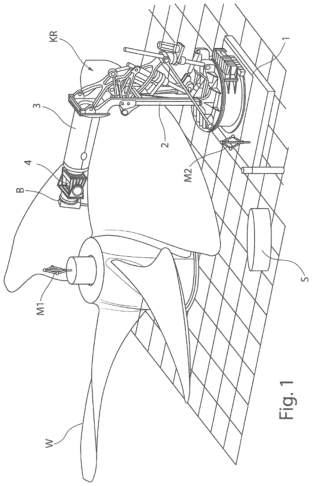
[0031]FIG. 1 shows a workpiece W in the form of a ship's propeller that is to be machined, which is to be provided with boreholes at certain predefined machining locations. Due to its size and the surface of workpiece W, which consists mainly of freeform surfaces, the only apparatus suitable for post-machining the workpiece is a large-scale, vertical articulated-arm robot KR with a boring arrangement B attached to the end face of the kinematic chain thereof, which has two arm members 2 and 3. Articulated-arm robot KR, which is described in full detail in document DE 10 2013 018 857 A1, is equipped with a robot arm which is secured to a base 1 that is rotatable about the vertical axis. The robot arm has two arm members 2 and 3 arranged one after the other in the manner of a kinematic chain, with which the first arm member 2 is mounted on base 1 to pivot about a second axis aligned orthogonally to the vertical axis. The second arm member 3 is attached to the first arm member 1 to pivo...


PUM

PropertyMeasurementUnit
sizeaaaaaaaaaa
diameteraaaaaaaaaa
diameteraaaaaaaaaa

Abstract

The invention relates to a method and an arrangement for introducing boreholes into a surface of a workpiece (W) mounted in a stationary manner using a boring tool which is attached to the end face of an articulated-arm robot (KR) and which can be spatially positioned by said robot. The method has the following method steps: —positioning the articulated-arm robot-guided boring tool at a spatial position which lies opposite a specified machining location on the workpiece surface at a specified distance therefrom, —producing a rigid mechanical connection which supports the end face of the articulated-arm robot (KR) on the workpiece and which can be released from the workpiece surface, and —machining the surface by moving the boring tool towards the machining location and subsequently engaging the boring tool with the workpiece (W) at the machining location on the workpiece surface while the end face of the articulated-arm robot (KR) is connected to the workpiece. The invention is characterized by the combination of the following method steps: the boring tool is moved towards the workpiece (W) by means of an NC advancing unit attached to the end face of the articulated-arm robot (KR), the boring process is monitored on the basis of information obtained using a sensor system which detects the position of the boring tool relative to the workpiece surface and which is attached to the end face of the articulated-arm robot (KR), and the boring process is terminated upon reaching a specified boring depth.

Description

CROSS REFERENCE TO RELATED APPLICATIONS[0001]Reference is made to International Application No. PCT / EP2016 / 061785 filed May 25, 2016, and German Application No. 102015210255.6 filed Jun. 3, 2015, which are incorporated herein by reference in their entirety.BACKGROUND OF THE INVENTIONField of the Invention[0002]The invention relates to a method and an arrangement for introducing boreholes, preferably in the form of blind holes, very accurately into a surface of a workpiece mounted in a stationary manner and having any shape using a boring tool which is attached to the end face of an articulated-arm robot and which can be spatially positioned by the robot.Description of the Prior Art[0003]Articulated-arm robots are widely used, versatile industrial robots, the kinematics for which is constructed from a plurality of arm members connected to each other in an articulated manner to guide and position end effectors such as tools for purposes of processing a workpiece. Of the many possible ...

Claims


Application Information

Patent Timeline
Patent Type & Authority Patents(United States)
IPC IPC(8): B23Q15/22B25J15/06B23Q15/00B23Q17/22B23B35/00B23B39/08B23B41/00B25J15/00B25J11/00B23Q3/08
CPCB23Q15/22B23Q15/00B23B35/00B23Q17/2241B25J15/0608B23B41/00B25J15/0019B25J15/0095B25J11/005B23B39/08B25J15/0616B23Q17/2233Y10S901/41B23B2215/76Y10S901/09B23B2215/81B23Q3/088Y10S901/47Y10S901/40B23B39/14B23Q1/25B25J9/10B25J9/1005B23Q1/48
Inventor WANNER, MARTIN CHRISTOPHDRYBA, STEFFENGRUENDLER, MIRKO
Owner FRAUNHOFER GESELLSCHAFT ZUR FOERDERUNG DER ANGEWANDTEN FORSCHUNG EV
Why Eureka
Try Eureka