Support structure for a filter element

a support structure and filter element technology, applied in the direction of filtration separation, membrane technology, separation processes, etc., can solve the problem of impossible to achieve the optimal compromise between structural performance and fluid permeability, as a rule, and achieve the effect of good fluid permeability and high mechanical strength

Active Publication Date: 2020-03-24
HYDAC FILTERTECHNIK GMBH
View PDF11 Cites 0 Cited by
  • Summary
  • Abstract
  • Description
  • Claims
  • Application Information

AI Technical Summary

Benefits of technology

[0004]An object of the invention is to provide an improved support structure for a filter element, which support structure is characterized by a high degree of mechanical strength while at the same time, being characterized by good fluid permeability.

Problems solved by technology

Material supports formed between the holes then form weak points in the support structure, making achieving an optimum compromise, as a rule, of structural performance and fluid permeability impossible.

Method used


Image

  • Support structure for a filter element
  • Support structure for a filter element
  • Support structure for a filter element

Examples


Embodiment Construction

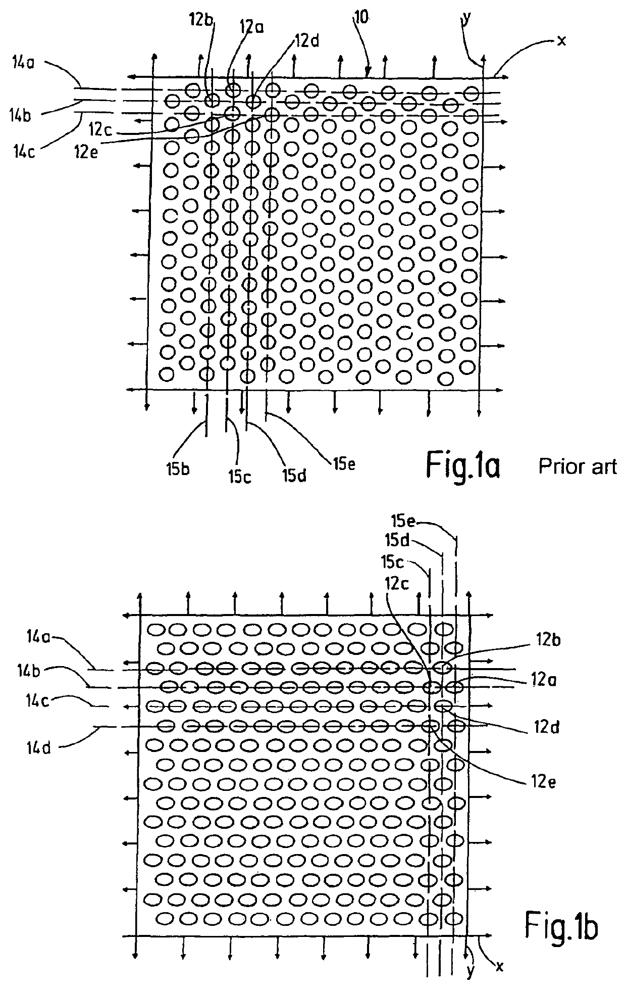
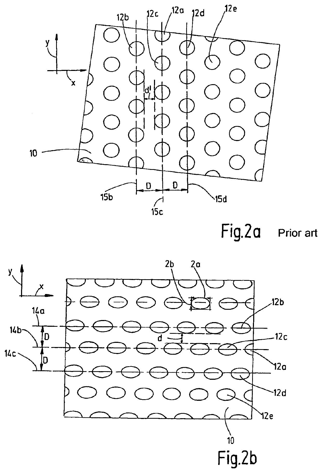
[0024]An illustration of the surface part 10 is shown in FIG. 1a and enlarged in FIG. 2a, which extends horizontally in the direction of the x-axis and vertically in the direction of the y-axis, and which, in principle, has a rectangular or, more specifically a square shape only in the respective illustrations. A plurality of fluid passage openings 12a-12e are formed in the surface part 10 Each opening has a circular cross-sectional shape, or in other words, a circular opening cross-section. The passage openings are uniformly disposed in rows 14a-14c along the direction of the x-axis and in columns 15b-15e along the direction of the y-axis. The rows 14a-14c and columns 15b-15e of the fluid passage openings 12a-12e are alternately offset from one another in such a way that a fluid passage opening 12d of a row 14b is axially disposed, when viewed in the direction of the x-axis, between the adjacent fluid passage openings 12a, 12c, 12e of the two nearest rows 14a, 14c. Accordingly, the...


PUM

PropertyMeasurementUnit
differential pressureaaaaaaaaaa
degree of mechanical strengthaaaaaaaaaa
flow resistanceaaaaaaaaaa

Abstract

A support structure (16) for a filter element includes at least one surface part (10), in which one or more fluid passage openings (12a-12e) with predetermined opening cross-sections are formed. The opening cross-section of at least one fluid passage opening (12a-12e) is at least partially elliptical-shaped.

Description

FIELD OF THE INVENTION[0001]The invention relates to a support structure for a filter element, comprising at least one surface part. One or more fluid passage openings having predetermined opening cross-sections are formed in the support structure.BACKGROUND OF THE INVENTION[0002]A support structure for a filter element is known from U.S. Pat. No. 5,783,067, for example. The known support structure forms the wall of a support tube, which encloses the outer surface of a filter medium, and which has a pattern of holes that form fluid passage openings. The fluid passages in the support tube are formed as rounded oblong holes, each of which has two side lines that extend parallel to one another, and two curved lines that connect the side lines to one another. The fluid passage openings, which are formed as oblong holes, are aligned in such a way that they each extend in a radial direction along the support tube.[0003]Good operating behavior of the filtering elements used is paramount fo...

Claims


Application Information

Patent Timeline
Patent Type & Authority Patents(United States)
IPC IPC(8): B01D29/13B01D29/11B01D29/21
CPCB01D29/111B01D29/13B01D29/21B01D2201/0415B01D2201/0407B01D2201/52
Inventor SCHWENDER, MATTHIASSCHMITZ, ANDREASKOCH, EDWINJOCHUM, STEFAN
Owner HYDAC FILTERTECHNIK GMBH
Why Eureka
Try Eureka