Low-power bowed rotor prevention system

a rotor and low-power technology, applied in the direction of efficient propulsion technologies, machines/engines, engine starters, etc., can solve the problems of undesirable engine restart or engine start, “bowed rotor” condition

Active Publication Date: 2020-03-24
RTX CORP
View PDF123 Cites 3 Cited by
  • Summary
  • Abstract
  • Description
  • Claims
  • Application Information

AI Technical Summary

Problems solved by technology

When this occurs thermal expansion may cause deflection of components of the engine which may result in a “bowed rotor” condition.
If a gas turbine engine is in such a “bowed rotor” condition it is undesirable to restart or start the engine.

Method used


Image

  • Low-power bowed rotor prevention system
  • Low-power bowed rotor prevention system
  • Low-power bowed rotor prevention system

Examples


Embodiment Construction

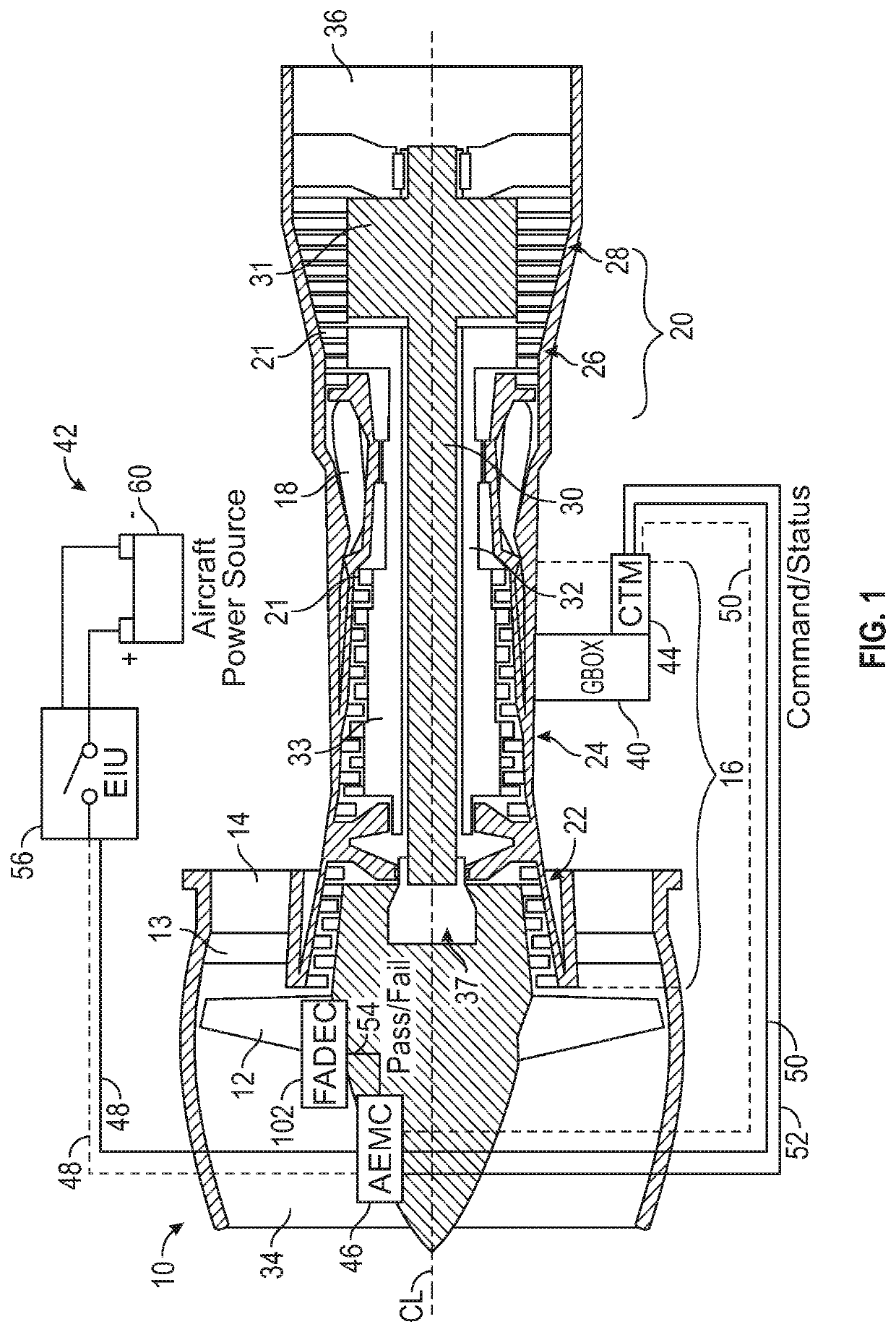
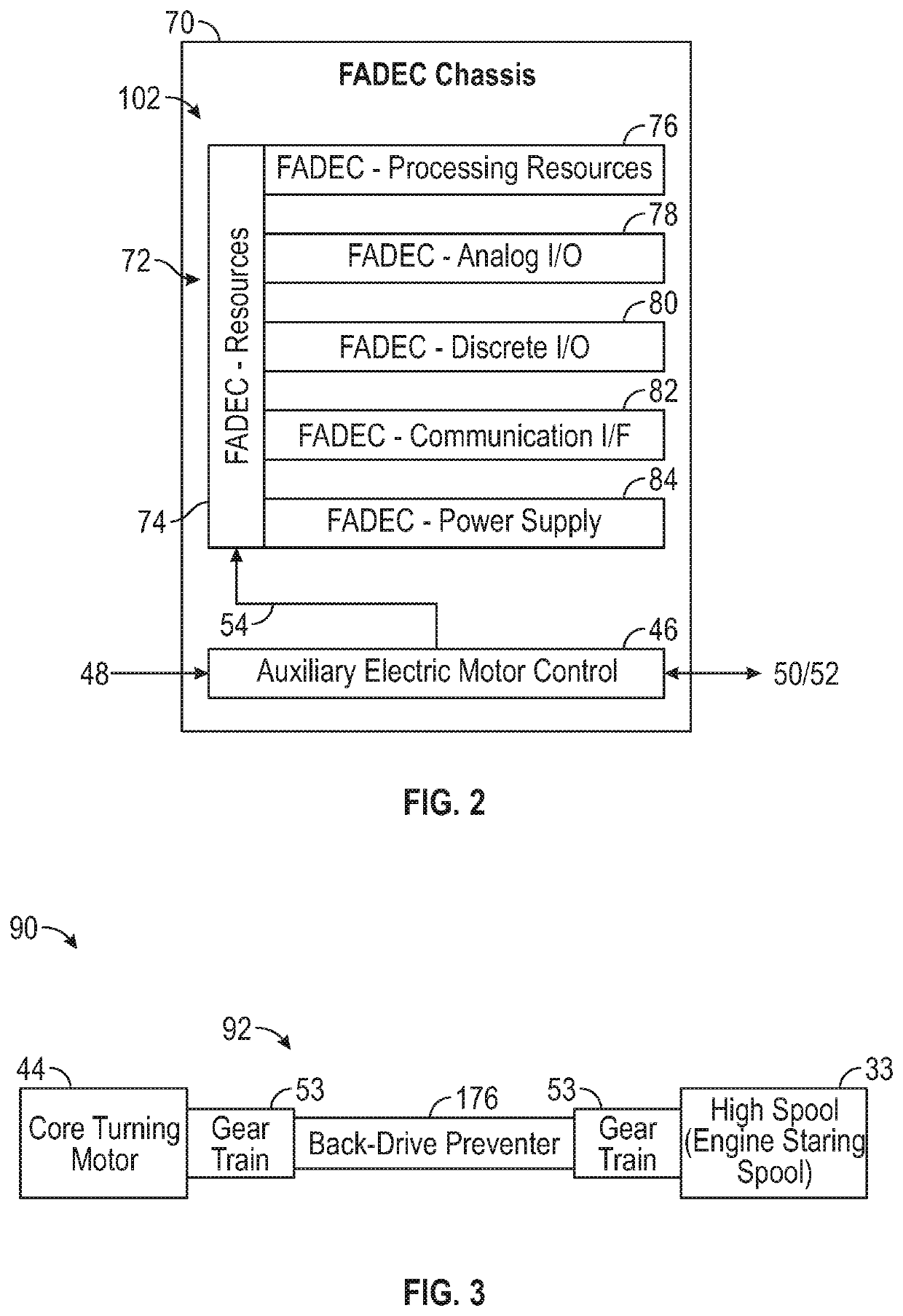
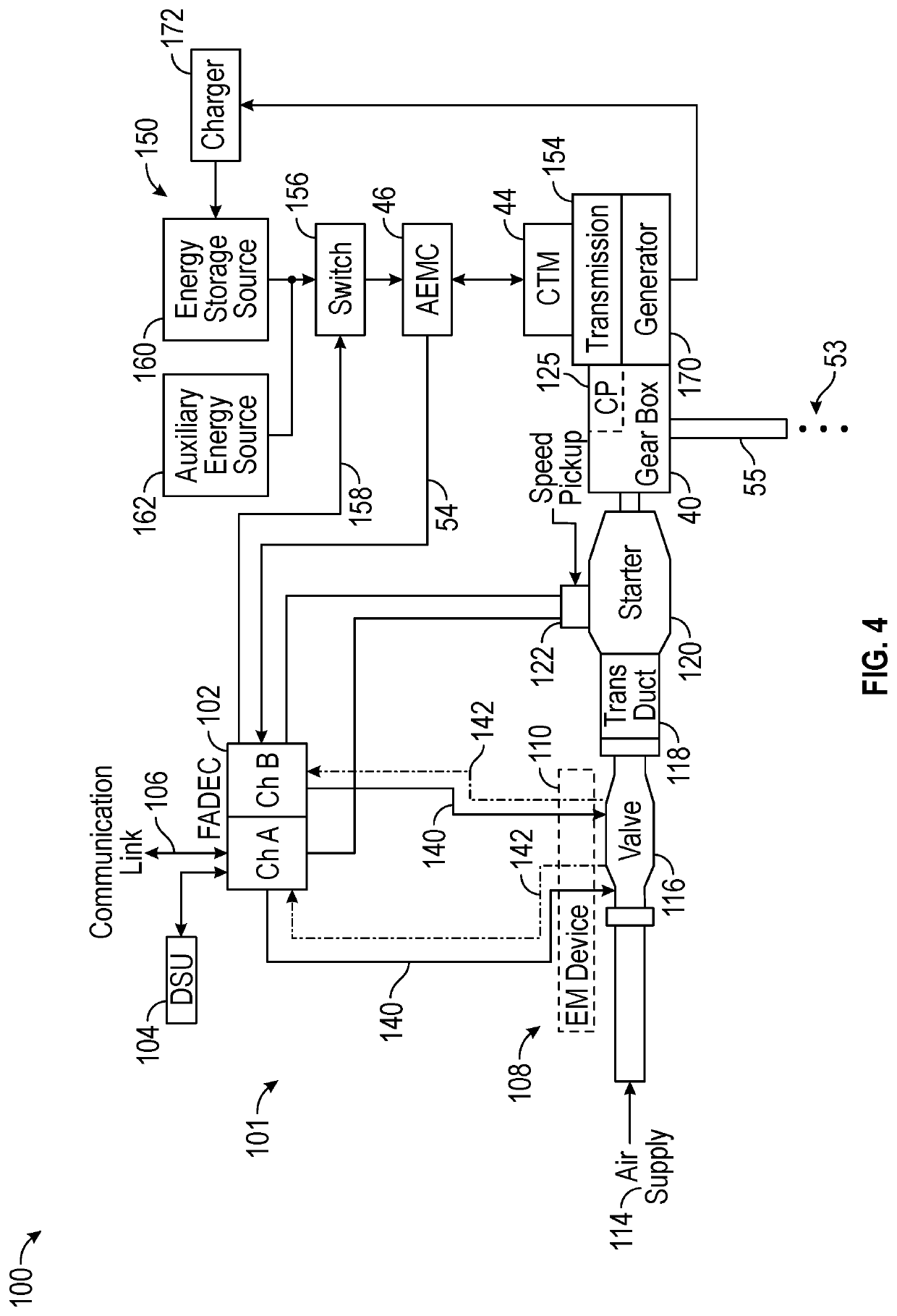
[0031]Various embodiments of the present disclosure are related to bowed rotor prevention in a gas turbine engine. Embodiments prevent a bowed rotor condition by using a core turning motor to drive rotation of the gas turbine engine under low power conditions. Embodiments use an auxiliary electric motor control (AEMC) to drive a core turning motor (CTM) to prevent a bowed rotor condition of the gas turbine engine based on aircraft power. The AEMC can isolate power requirements from a full authority digital engine control (FADEC) that controls operation of the gas turbine engine, such that the FADEC need not be fully operational and powered while the AEMC controls the CTM. The AEMC can be operable to monitor the duration of engine core rotation and report a pass / fail status, for instance, upon a subsequent engine start process performed by the FADEC. Embodiments consume less than 500 watts of power by the AEMC and the CTM combined while performing core turning (i.e., bowed rotor prev...


PUM


Abstract

A bowed rotor prevention system for a gas turbine engine includes a core turning motor operable to drive rotation of an engine core of the gas turbine engine. The bowed rotor prevention system also includes an auxiliary electric motor control operable to control the core turning motor to drive rotation of the engine core using electric power while a full authority digital engine control that controls operation of the gas turbine engine is either depowered or in a power state that is less than a power level used by the full authority digital engine control in flight operation.

Description

CROSS-REFERENCE TO RELATED APPLICATIONS[0001]This patent application claims priority to U.S. Provisional Application No. 62 / 301,163, filed Feb. 29, 2016, which is incorporated herein by reference in its entirety.BACKGROUND[0002]This disclosure relates to gas turbine engines, and more particularly to a bowed rotor prevention system.[0003]Gas turbine engines are used in numerous applications, one of which is for providing thrust to an aircraft. When a gas turbine engine of an aircraft has been shut off for example, after an aircraft has landed at an airport, the engine is hot and due to heat rise, the upper portions of the engine will be hotter than lower portions of the engine. When this occurs thermal expansion may cause deflection of components of the engine which may result in a “bowed rotor” condition. If a gas turbine engine is in such a “bowed rotor” condition it is undesirable to restart or start the engine.[0004]Accordingly, it is desirable to provide a method and / or apparatu...

Claims


Application Information

Patent Timeline
Patent Type & Authority Patents(United States)
IPC IPC(8): F01D25/36F01D21/20F02C7/277F02C7/275F01D21/00F02C7/32F01D19/00
CPCF01D25/36F01D21/20F01D19/00F02C7/277F02C7/275F01D21/00F05D2260/4031F02C7/32F05D2220/323F05D2260/85Y02T50/60
Inventor CLAUSON, JESSE W.SCHWARZ, FREDERICK M.
Owner RTX CORP
Why Eureka
Try Eureka