Method of operating a supercharger

a supercharger and supercharger technology, applied in the direction of batteries/cells, machines/engines, transportation and packaging, etc., can solve the problems of more expensive manufacturing, and less efficient operation of larger engines, and achieve the effect of constant speed

Active Publication Date: 2010-11-04
NEXXTDRIVE LTD +1
View PDF17 Cites 42 Cited by
  • Summary
  • Abstract
  • Description
  • Claims
  • Application Information

AI Technical Summary

Benefits of technology

[0022]The method may also include operating the first electrical machine as a motor to assist the engine when the accelerator is depressed during, for example, a gear change, when out of gear, or when the clutch is disengaged. This causes the engine to have the appearance of “revving” more freely than would otherwise be the case. The second electrical machine may also be operated as a motor in such circumstances.
[0023]The method may also include operating the first electrical machine as a motor or a generator when the engine is idling or close to idling so as to cause the engine to operate with more constant speed than would otherwise be the case. This reduces cyclic variations in engine speed that would otherwise exist at or near id

Problems solved by technology

Larger engines are, however, less efficient to operate

Method used


Image

  • Method of operating a supercharger
  • Method of operating a supercharger
  • Method of operating a supercharger

Examples


second embodiment

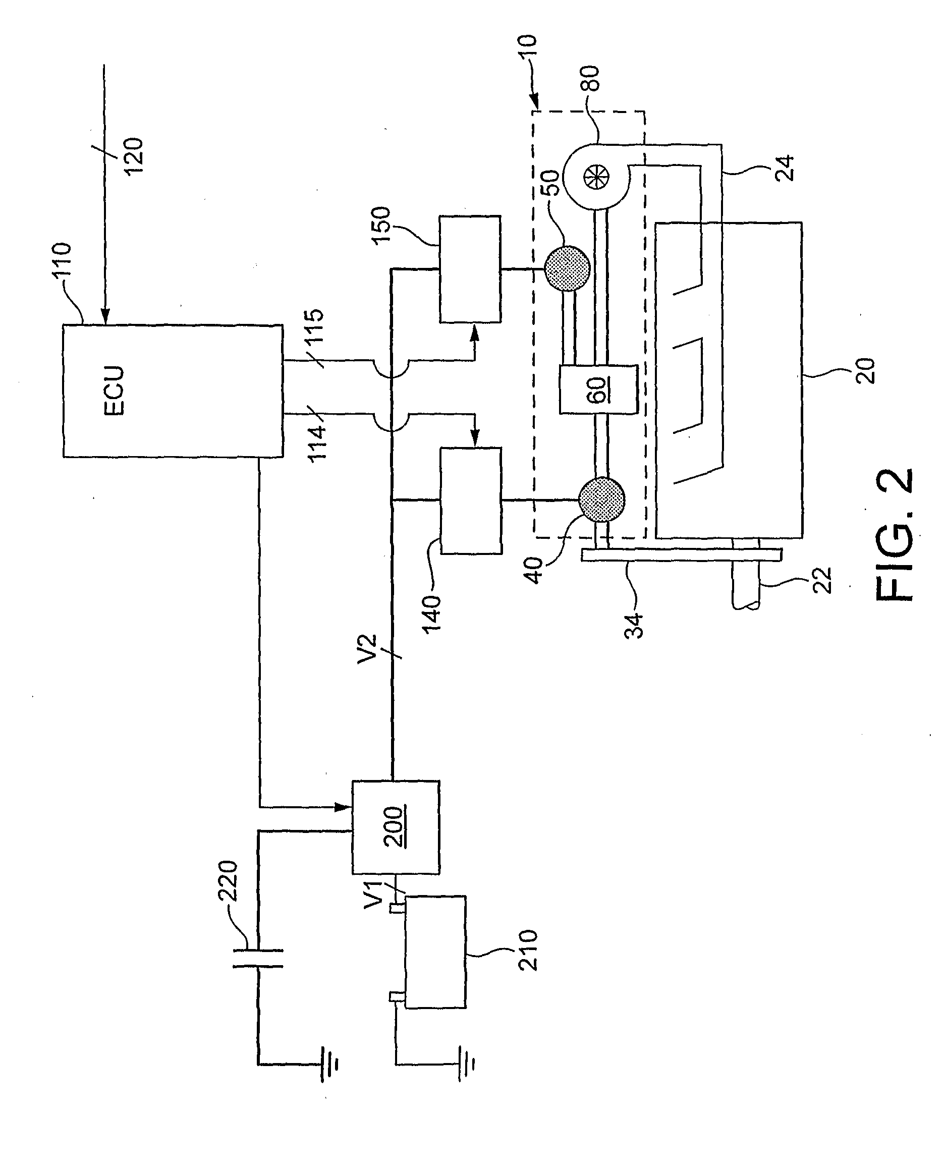
[0074]In this invention, the method may additionally provide for a mode of operation in which the first motor-generator 40 is operated as a motor to assist the engine 20 when the engine is idling, such that the engine can be idled at a speed lower than what would otherwise be its idling speed, thereby saving fuel.

third embodiment

[0075]In third embodiment, the method may additionally stop the engine 20 when the vehicle comes to a rest and then start the engine again before accelerating from rest. This may be achieved by operating the first motor-generator 40 as a motor to start the engine and as a generator to stop the engine.

[0076]In a third embodiment, the method may include a mode of operation in which the first motor-generator 40 is operated as a generator to slow the engine 20 and hence the vehicle under braking. The method may enter this mode of operation upon the ECU receiving an input indicative of a brake pedal of the vehicle being depressed. When operated as a generator in this way, the first motor-generator 40 may be used to recharge the battery 210 and also the capacitor 220. Thus, this mode of operation may be considered as a regenerative-braking mode.

fifth embodiment

[0077]In a fifth embodiment, it is envisaged that the ECU 110 be further arranged such that control of the supercharger in accordance with the method is integrated into both a torque control path and a charge control path of the ECU 110. It will be appreciated that existing engine management systems that employ Engine Control Units include a torque control path and a charge control path. This integration would allow the first motor-generator 40 to be used selectively to contribute to or oppose engine torque. Thus, the first motor-generator 40 may be used to make torque “interventions” in the output of the engine 20. In this way, and with appropriate feedback, closed-loop engine torque control can be provided. Similarly, integrating control of the supercharger 10 into the charge control path can be used to deliver closed-loop boost pressure control.

[0078]Integration of control of the supercharger into the charge control path may be used to control the air massflow and / or boost pressu...


PUM


Abstract

A method of operating a supercharger (10) for an automotive engine (20) is disclosed. A supercharger (10) has an input shaft (30) for coupling to a crank shaft (22) of the engine and also for coupling to the rotor of a first electrical machine (40) and the annulus of an epicyclic gear train (60). An output shaft (70) is connected to a compressor (80) and a sun gear of the epicyclic gear train (60). A carrier carrying planet gears of the epicyclic gear train (60) is connected to the rotor of a second electrical machine (50). The first electrical machine (40) is selectively operable to supply electrical energy to the second electrical machine (50). The second electrical machine (50) is selectively operable as a motor or a generator to accelerate or decelerate the compressor (80), thereby tending to increase or decrease the power output of the engine. The first electrical machine (40) is selectively operable as a motor or a generator to control the torque transmitted from the input shaft (30) back to the crank shaft (22) caused by operation of the second electrical machine (50).

Description

TECHNICAL FIELD[0001]This invention relates to a method of operating a supercharger for an automotive engine.BACKGROUND[0002]WO-A1-2004 / 072449, the disclosure of which is incorporated herein in its entirety, describes an automotive air blower in the form of a supercharger for use with an automotive engine. The supercharger differs from a conventional supercharger in being operable to augment rotary power from the engine crankshaft with rotary power from one or more electric motors housed in a body of the supercharger.[0003]More specifically, the supercharger includes an input shaft for coupling by a transmission belt to the crankshaft of the engine, and also includes an output shaft to which is fitted an air impellor. The supercharger further includes an epicyclic gear train, and first and second motor-generator electrical machines. The arrangement is such that the input shaft is coupled to the annulus of the epicyclic gear train and to the rotor of one of the electrical machines; t...

Claims


Application Information

Patent Timeline
IPC IPC(8): F02B33/00F04D27/02
CPCB60K6/24B60K6/46B60K6/485B60W10/06B60W10/08B60W20/00Y02T10/6295F02B39/04F02B39/10Y02T10/6217Y02T10/6226Y02T10/6286F02B33/40B60L15/20B60L50/61B60L2240/423B60L2240/443F04D25/028F04D25/06Y02T10/62Y02T10/64Y02T10/70Y02T10/72Y02T10/7072
Inventor MCDONALD-WALKER, RUARAIDH
Owner NEXXTDRIVE LTD
Why Eureka
Try Eureka