Hybrid water pressure energy accumulating wind turbine and method

Inactive Publication Date: 2011-06-09
KAMENOV KAMEN GEORGE
View PDF6 Cites 35 Cited by
  • Summary
  • Abstract
  • Description
  • Claims
  • Application Information

AI Technical Summary

Benefits of technology

[0042]In the present invention the major difference from the prior art is the use of water tank reservoirs as pressure vessels for storing energy. This results in several advantages of

Problems solved by technology

Wind turbines have been used for production of electricity although such use has typically been limited to the production of small amounts of direct current (DC) electricity.
The natural forms of energy are effectively inexhaustible and are typically available in different forms throughout the world.
Shortly after beginning the operation, a main bearing and a blade failed.
Because of World War II, the machine was never repaired and it was subsequently dismantled.
When the wind is weak, the surface gets bigger.
This clearly illustrates that converting wind energy directly into electricity utilizing wind turbines involves elaborate equipment and requires high initial costs.
However, it has the disadvantage of converting wind energy to hydraulic power.
Therefore, Hanley's invention, assuming its technical feasibility, involves elaborate equipment and requires high initial costs.
This is especially important for offshore facilities, where turbine breakdowns are always very expensive.
Wind turbines without gearboxes are generally heavier than conventional units and also more expensive to produce.
The disadvantages of wind energy are that it is diluted, unpredictable, and requires high initial costs.
Wind energy is only available when the wind is blowing within a particular range of wind speeds, i.e., the turbine cannot operate at wind speeds (also called velocities) below the minimum speed and cannot safely operate above the maximum speed.
Further, wind power is dependent on the location because it is only seasonal in many areas of the world.
The major disadvantages of the currently used wind turbines are:Each has its own electric generating equipment, a gearbox linked to an AC generator

Method used


Image

  • Hybrid water pressure energy accumulating wind turbine and method
  • Hybrid water pressure energy accumulating wind turbine and method
  • Hybrid water pressure energy accumulating wind turbine and method

Examples


Example

[0083]Detailed descriptions of the preferred embodiment are provided herein. It is to be understood, however, that the present invention may be embodied in various forms. Therefore, specific details disclosed herein are not to be interpreted as limiting, but rather as a basis for the claims and as a representative basis for teaching one skilled in the art to employ the present invention in virtually any appropriately detailed system, structure or manner.

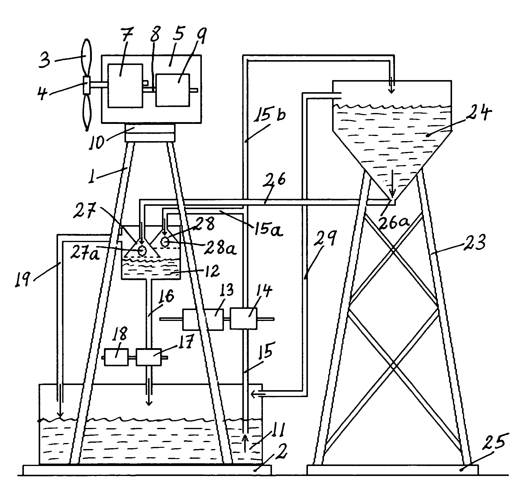
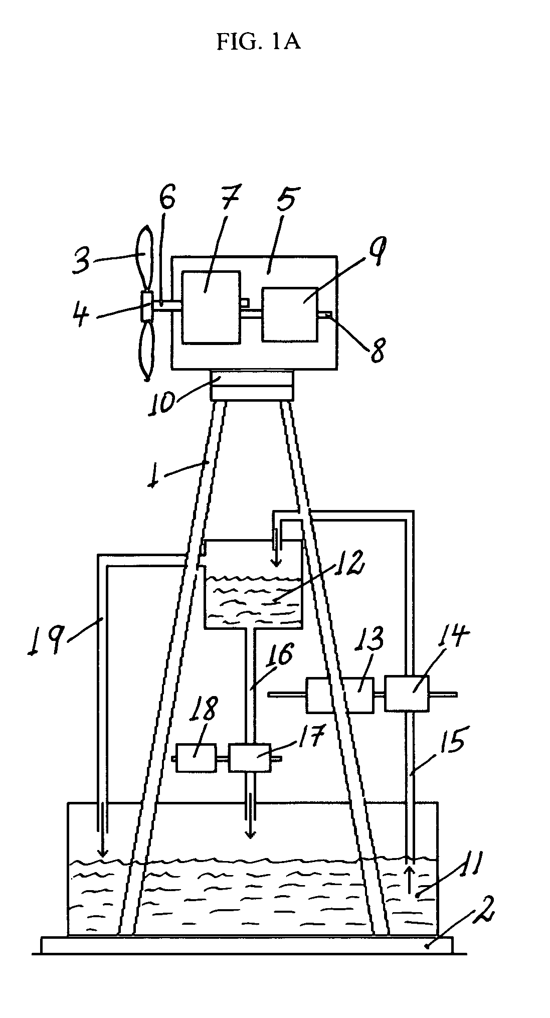
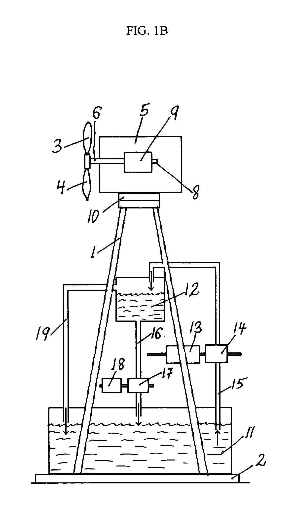
[0084]The present invention is directed to wind turbine towers or tower systems configured for storing water in water containers within the tower structure itself and / or next to it and for generating electricity using the potential energy of the stored water. Briefly, the towers of modern, utility-scale wind turbine tower systems are typically metal or cement structures with a circular cross section that in addition to supporting a nacelle are adapted, according to the present invention, to store water. To achieve this functionality,...


PUM


Abstract

A hybrid water pressure energy accumulating, wind turbine tower assembly used to directly propel water pumps to raise water from low elevation reservoir(s) to high elevation reservoir(s) where it is used as a potential energy. The wind tower assembly includes a wind turbine having propeller with a rotor, a generator driven by the rotor and a yaw assembly attached to a tower with a foundation. The tower includes in-tower storage reservoirs configured for storing water. The in-tower storage reservoirs could be defined by lower and upper water storage containers attached to the inner or outer surface of the tower that might be connected to other neighboring reservoir(s). The wind turbine may be of the vertical or horizontal-axis type and may be installed inside a residential or commercial building. The lifted water is used to generate electricity utilizing a hydropower generator.

Description

TECHNICAL FIELD[0001]This invention relates generally to the field of alternative energy generating wind turbines used for generating electricity, and more specifically to hybrid water pressure energy accumulating wind turbine towers modified for storing water as potential energy for immediate or later use as electric energy and for transmission over the grid. The above disclosure sets forth a number of embodiments of the present invention. Other arrangements or embodiments, not precisely set forth, could be practiced under the teaching of the present invention and as set forth in the following claims.BACKGROUND OF THE INVENTION[0002]Natural energy is available throughout the world in various forms such as wind, solar, tidal and wave energy. Wind turbines have been used for production of electricity although such use has typically been limited to the production of small amounts of direct current (DC) electricity.[0003]Conventional sources of energy for the production of electricity ...

Claims


Application Information

Patent Timeline
IPC IPC(8): F03D1/00F03D3/00
CPCF03B13/06F03D9/025Y02E60/17Y02E10/22Y02E10/72Y02B10/30F03D9/008F03D9/11F03D9/14F03D9/25F03D15/10Y02B10/70Y02E10/20Y02E60/16Y02E70/30
Inventor KAMENOV, KAMEN GEORGE
Owner KAMENOV KAMEN GEORGE
Why Eureka
Try Eureka