
Device for robot-assisted surgery

a robot and surgery technology, applied in the field of robot-assisted surgery, can solve the problems of contaminated surgical instruments and/or endoscopes, contamination of body fluids and/or tissue, contamination of material, etc., and achieve the effect of convenient and safe connection and easy handling

Active Publication Date: 2020-03-31
AVATERAMEDICAL GMBH
View PDF23 Cites 9 Cited by
  • Summary
  • Abstract
  • Description
  • Claims
  • Application Information

AI Technical Summary

Benefits of technology

[0010]If it is necessary to couple devices of category 1 or category 2 to devices of category 3, then a sterile interface is required which prevents contamination of the devices of category 1 or category 2 by the non-sterile devices of category 3 and, vice versa, prevents a contamination of the devices of category 3 since these are generally technically designed as autoclavable components that cannot be sterilized. The realization of devices as autoclavable components that can be sterilized requires a particular technical design of the device for the sterilization process so that a higher development effort as well as considerable validation effort for proving the effectiveness of the sterilization process are necessary for this. For such a proof, it is in particular necessary, multiple times in succession, to contaminate and sterilize the device and to perform an effectiveness check of the sterilization as well as a functionality check after sterilization. Here, proof has to be furnished that after each sterilization the devices are reliably sterilized and thus could be used again.
[0063]Further, it is advantageous when the arrangement has several devices for robot-assisted surgery according to claim 1 or according to a mentioned development. The input device has preferably at least two actuating elements actuatable by a user, wherein the input device detects a change of position in space of each actuating element and generates each time an input command corresponding to the detected change of position in space. Dependent on each input command, the control unit generates at least one control command each by which the same or a scaled up / down change of position in space of at least one end of a surgical instrument, at the distal end of which the sterile unit is arranged, of the device for robot-assisted surgery assigned to the respective actuating element at the point in time of the actuation is caused and / or by which an actuation or a scaled actuation of this surgical instrument is caused. As a result, the operation can be performed with several instruments which are present in the operating field at the same time or which, in the case of laparoscopic surgeries, are present in the abdominal cavity of the patient at the same time.

Problems solved by technology

By means of the telemanipulator system surgical instruments and / or endoscopes are controlled in their position and orientation on the basis of user inputs and, in doing so, inevitably come into physical contact with the patient to be operated so that the surgical instruments and / or endoscopes are contaminated with body fluids and / or tissue of the operated patient.
Category 1: The material is sterile and is contaminated during the surgical operation.

Method used


Image

  • Device for robot-assisted surgery
  • Device for robot-assisted surgery
  • Device for robot-assisted surgery

Examples


second embodiment

[0142]FIG. 20 shows a detail of an instrument unit 1300 with a sterile unit 1400 and a surgical instrument 1500 according to a In contrast to the instrument unit 300, the sterile unit 1400 of the instrument unit 1300 has no sterile flaps but a jalousie 1410 for covering the driven elements in a sterile manner. The further structure and the function of the instrument unit 1300 corresponds to the structure and the function of the instrument unit 300 according to FIGS. 1 to 19.

[0143]FIG. 21 shows a detail of a sterile covering 1038 with a sterile lock 1200 which in contrast to the sterile lock 200 has no sterile flaps but a jalousie 1210 for shielding drive elements of the coupling unit 100 in a sterile manner. The jalousie 1410 of the coupling unit 1400 and the jalousie 1210 of the sterile lock 1200 are opened in a suitable manner by a mechanical engagement when connecting the sterile unit 1400 to the sterile lock 1200 or the sterile unit 1400 to the sterile lock 200 or the sterile u...

third embodiment

[0144]In FIG. 22, a detail of an instrument unit 2300 with a sterile unit 2400 is shown. The sterile unit 2400 has no elements for covering the driven elements in a sterile manner so that this instrument unit 2400 is immediately removed from the sterile area 39 after separation from the sterile lock 200, 1200 or after separation from a further sterile lock 2200 shown in FIG. 23.

[0145]The sterile cover 2038 shown in FIG. 23 comprises a sterile lock 2200 which is couplable to the coupling unit 100 just like the sterile unit 200. In contrast to the sterile lock 200, the sterile lock 2200 has no lock flaps but comprises a foil provided with predetermined breaking points indicated by means of dotted lines, which foil is torn open along the predetermined breaking points when connecting a sterile unit 400, 1400, 2400 to the sterile lock 2200 so that a direct coupling of the drive elements 110 to 116 of the coupling unit 100 with the driven elements 408 to 414 is easily possible. Preferabl...


PUM


Abstract

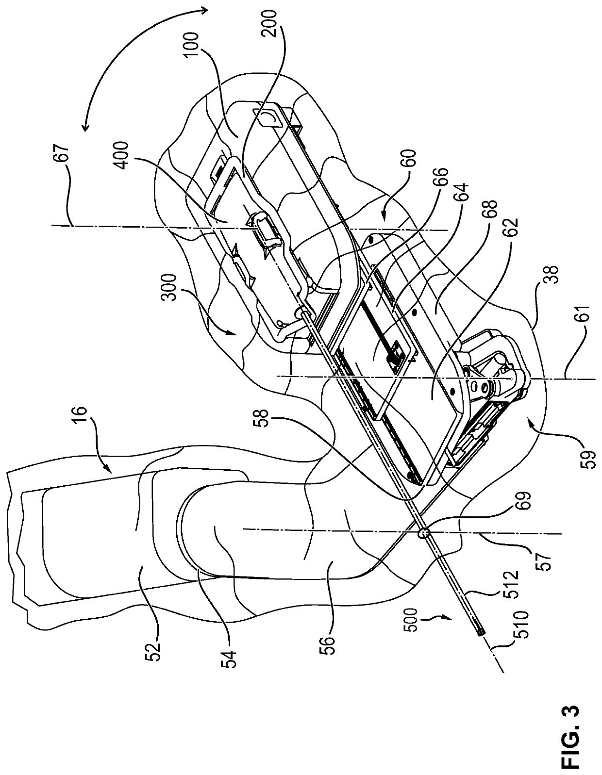
A device for robot-assisted surgery, comprising at least one non-sterile manipulator arm (12) having a coupling unit (100) with drive elements. The device further has an instrument unit (300) which comprises a surgical instrument (500) and a sterile sterile unit (400) for coupling the surgical instrument (500) to the drive elements of the coupling unit (100). The coupling unit (100) comprises a translatory drive element (110, 112) for generating a translatory drive movement and a rotatory drive element (114, 116) for generating a rotatory drive movement. The sterile unit (400) has a translationally driven element (408, 410) couplable to the translatory drive element (110, 112) and a rotationally driven element (412, 414) couplable to the rotatory drive element (114, 116). The device has a sterile lock (200) which is capable of being coupled to the coupling unit (100) and to the sterile unit (400).

Description

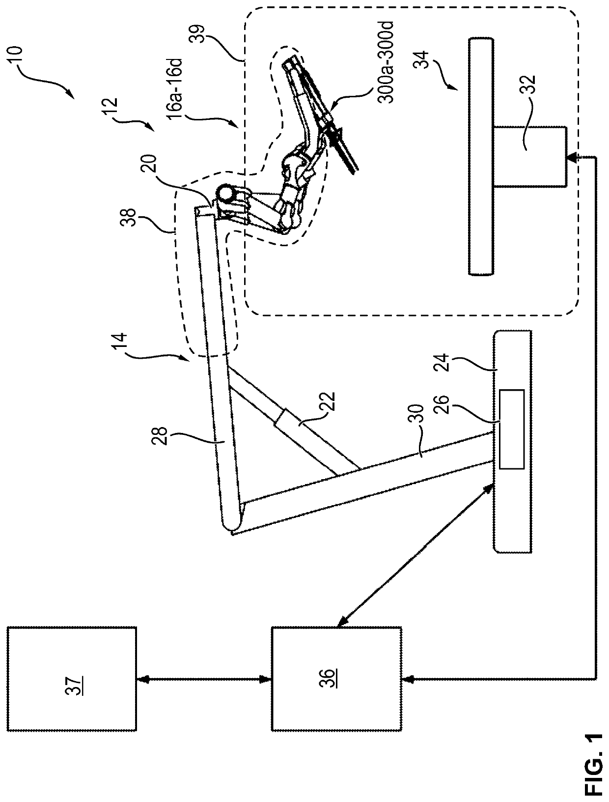
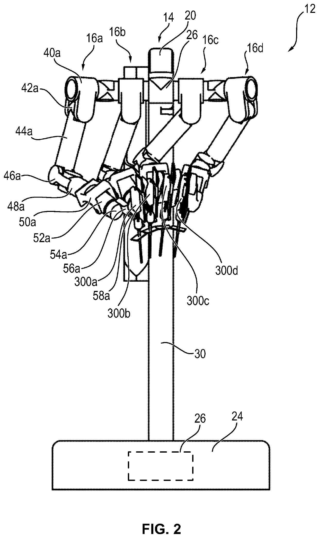
BACKGROUND OF THE INVENTION[0001]Technical Field[0002]The invention relates to a device for robot-assisted surgery, comprising at least one manipulator arm arranged in a non-sterile area and having a coupling unit which has at least a first transmitting means. The device has at least one sterile unit arranged in a sterile area and having at least a second transmitting means and a sterile cover for shielding the manipulator arm from the sterile area.[0003]Discussion[0004]In minimally-invasive surgery, so-called telemanipulator systems, also referred to as robot-assistance systems, are increasingly used. The sterile surgical field is protected against the non-sterile elements of the telemanipulator system by means of a sterile cover. By means of the sterile cover both a contamination of the sterile surgical field and a contamination of the telemanipulator system by body fluids and / or tissue of the operated patient or of the surgical staff is prevented. This reduces the risk of cross-c...

Claims


Application Information

Patent Timeline
Patent Type & Authority Patents(United States)
IPC IPC(8): A61B34/30A61B1/00A61B34/35A61B46/10A61B34/37A61B90/40A61B18/14A61B17/00
CPCA61B34/37A61B34/30A61B18/1492A61B1/00149A61B46/10A61B90/40A61B34/35A61B2034/302A61B2017/00477A61B2034/301
Inventor KARGUTH, ANDREASTROMMER, CHRISTIANSEEBER, MARCEL
Owner AVATERAMEDICAL GMBH
Learn More