Method for detecting defective printing nozzles in an inkjet printing machine

a technology of inkjet printing machine and defective nozzle, which is applied in the direction of printing, power drive mechanism, electrical apparatus, etc., can solve the problem of not providing any reliable correlation between detected prints

Active Publication Date: 2020-03-31
HEIDELBERGER DRUCKMASCHINEN AG
View PDF10 Cites 1 Cited by
  • Summary
  • Abstract
  • Description
  • Claims
  • Application Information

AI Technical Summary

Benefits of technology

[0021]Another preferred development of the method of the invention in this context is that in the analysis of the recorded area coverage element, influences of the image sensor are eliminated by shading correction. In order to make the analysis of the recorded area coverage element as error-free as possible, influences of the image sensor on the digital image that it generated and forms the basis of the analysis of the area coverage element, are reduced as much as possible. Shading correction is done by a comparison with the substrate. In this way, light and shade effects in the digital image of the recorded area coverage element may be reliably eliminated by shading correction. This is important to prevent the analysis algorithm from detecting print defects that do not exist on the printed area coverage element but are only introduced into the digital image of the recorded area coverage element by the image recording process.
[0023]An added preferred development of the method of the invention in this context is that during the analysis of the recorded area coverage element, the computer makes a trend adjustment to increase the signal-to-noise ratio. The analysis of the area coverage element is done in such a way that the recorded tone values that have been established by the computer are processed to create a tone value signal. The tone value signal is the basis for the detection of the print defects that are present in the area coverage element. In order to make this detection less prone to errors, it is thus expedient to detect systematic influences on the tone value signal through the location and to reduce the tone values in the signal by these effects. Due to this trend adjustment, print defects such as white lines may be more easily detected during the analysis.
[0027]An additional preferred development of the method of the invention in this context is that during the examination of the detected print defects in terms of the established printing nozzle parameters of the geometrically close printing nozzles, the computer applies a classification model that is a function of a number of parameters such as the phase and amplitude values of a tone value signal generated from the established printing nozzle parameters. The computer applies a classification model to make the examination of the detected regions exhibiting print defects in terms of the printing nozzle parameters obtained from the printing nozzle test chart more efficient. This classification model is applied to all regions that are known from the analysis of the area coverage element. The classification model depends on a number of parameters such as the phase and amplitude values. Since the area coverage element is used for every print color that is used in the printing operation because every print color, i.e. process color, is naturally printed by a separate print head with its own printing nozzles, the classification model is likewise adapted for every process color that is used.

Problems solved by technology

As described in the introduction, in most cases, missing nozzle detection in a printed image (and a standardized printed image is precisely what an area coverage element actually is) does not provide any reliable correlation between a detected print defect and a specific printing nozzle.

Method used


Image

  • Method for detecting defective printing nozzles in an inkjet printing machine
  • Method for detecting defective printing nozzles in an inkjet printing machine
  • Method for detecting defective printing nozzles in an inkjet printing machine

Examples


Embodiment Construction

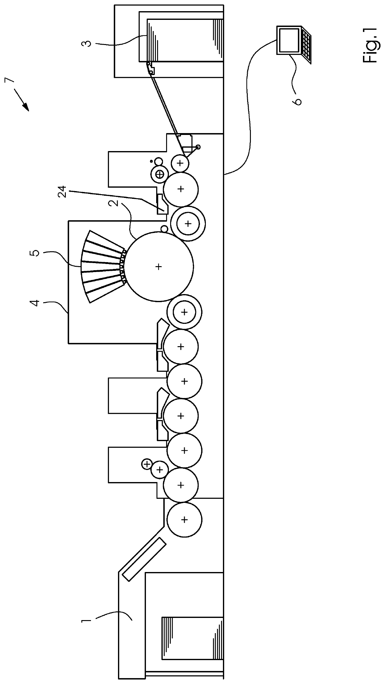
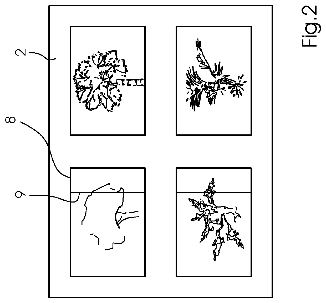
[0040]Referring now in detail to the figures of the drawings, in which mutually corresponding elements have the same reference symbols, and first, particularly, to FIG. 1 thereof, it is seen that the field of application of the preferred exemplary embodiment is an inkjet printing machine 7. FIG. 1 shows an example of the fundamental construction of such a machine 7, including a feeder 1 for feeding a printing substrate 2 to a printing unit 4 where it receives an image printed by print heads 5, as well as a delivery 3. The inkjet printing machine 7 is a sheet-fed inkjet printing machine 7 controlled by a control unit 6. As described above, individual printing nozzles 23 (see FIG. 6) in the print heads 5 in the printing unit 4 may fail while the printing machine 7 is in operation. Such a failure results in white lines 9 or, in the case of multicolor prints, in distorted color values. An example of such a white line 9 in a printed image 8 is shown in FIG. 2.

[0041]A preferred embodiment...


PUM


Abstract

A method for detecting defective printing nozzles in an inkjet printing machine includes printing a multi-row printing nozzle test chart formed of horizontal rows of equidistant vertical lines periodically underneath one another, with only printing nozzles in a print head contributing to every row of the test chart corresponding to the horizontal rows. An area coverage element geometrically associated with the test chart is printed, both elements are recorded by an image sensor and analyzed by the computer. The computer analyzes the recorded area coverage element to detect print defects and allocates defects to a region of geometrically close printing nozzles. An analysis of the test chart in the region identifies nozzles causing the defect. Defective printing nozzles are detected based on thresholds, the detected printing nozzles are then compensated, and in the analysis of the recorded area coverage element, influences of the sensor are eliminated by shading correction.

Description

CROSS-REFERENCE TO RELATED APPLICATION[0001]This application claims the priority, under 35 U.S.C. § 119, of German Patent Application DE 10 2018 202 027.2, filed Feb. 9, 2018; the prior application is herewith incorporated by reference in its entirety.BACKGROUND OF THE INVENTIONField of the Invention[0002]The present invention relates to a method for detecting defective printing nozzles in an inkjet printing machine.[0003]The technical field of the invention is the field of digital printing.[0004]In digital printing, namely in inkjet printing, a malfunctioning of individual printing nozzles of the print head of the inkjet printing machine is a common phenomenon. Those malfunctions include a plurality of potential types of defects, from nozzles that print a reduced ink drop volume to nozzles that print dots at the wrong place i.e. that print at an angle, and even printing nozzles that fail completely. Foreign bodies, in particular dust particles that have entered the printing nozzle ...

Claims


Application Information

Patent Timeline
Patent Type & Authority Patents(United States)
IPC IPC(8): B41J2/21B41J2/165B41J29/393H04N1/401B41J25/00
CPCH04N1/4015B41J2/16585B41J2/2142B41J2/2146B41J2/16579B41J2/2139B41J29/393B41J2029/3935B41J2025/008B41J2/165B41J2/135B41J2/14
Inventor MUEHL, JOHANNESKOEHLER, HANSSTENZEL, ROLANDHENN, ANDREASMAYER, MARTINNEEB, STEFFENMUTH, FRANKKRIEGER, JANNORRICK, NICKLAS RAYMONDABOSETTA, MINA
Owner HEIDELBERGER DRUCKMASCHINEN AG
Why Eureka
Try Eureka