
Lamination device

a technology of lamination device and electrode assembly, which is applied in the direction of sustainable manufacturing/processing, final product manufacturing, electrochemical generators, etc., can solve the problem of taking a lot of time to perform the operation, and achieve the effect of preventing the formation of bonding defects of the electrode assembly, improving working efficiency, and easy attachmen

Active Publication Date: 2020-03-31
LG ENERGY SOLUTION LTD
View PDF23 Cites 0 Cited by
  • Summary
  • Abstract
  • Description
  • Claims
  • Application Information

AI Technical Summary

Benefits of technology

The solution enhances the fixing force of the pattern film, prevents bonding defects, and improves working efficiency by automatically winding and securing the film around the roller using a shape-memory alloy deformation member.

Problems solved by technology

However, in the lamination device, the pattern film may move because a taped portion of the pattern film is gradually weakened by the heat and the pressure to cause bonding defects.
Particularly, the lamination device has a problem in which the pattern film has to be taped on a circumferential surface of the roller, and thus, it takes a lot of time to perform the operation.

Method used


Image

  • Lamination device
  • Lamination device
  • Lamination device

Examples


first embodiment

Lamination Device of the Present Invention

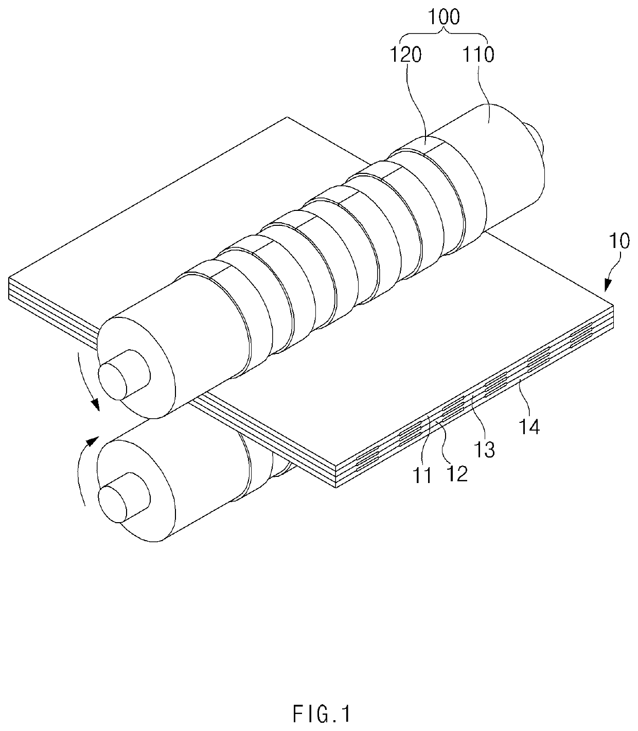
[0034]As illustrated in FIG. 1, a lamination device according to a first embodiment of the present invention is configured to press a surface of an electrode assembly 10 by using heat and a pressure, thereby embodying a pattern. The lamination device includes a pattern roller part 100 for embodying the pattern on the electrode assembly 10.

[0035]Referring to FIG. 1, the electrode assembly 10 includes a radical unit in which a plurality of electrodes 11 and 12 and a plurality of separators 13 and 14 are alternately stacked or has a structure in which two or more radical units are stacked. Here, the plurality of electrodes 11 and 12 may be a positive electrode and a negative electrode.

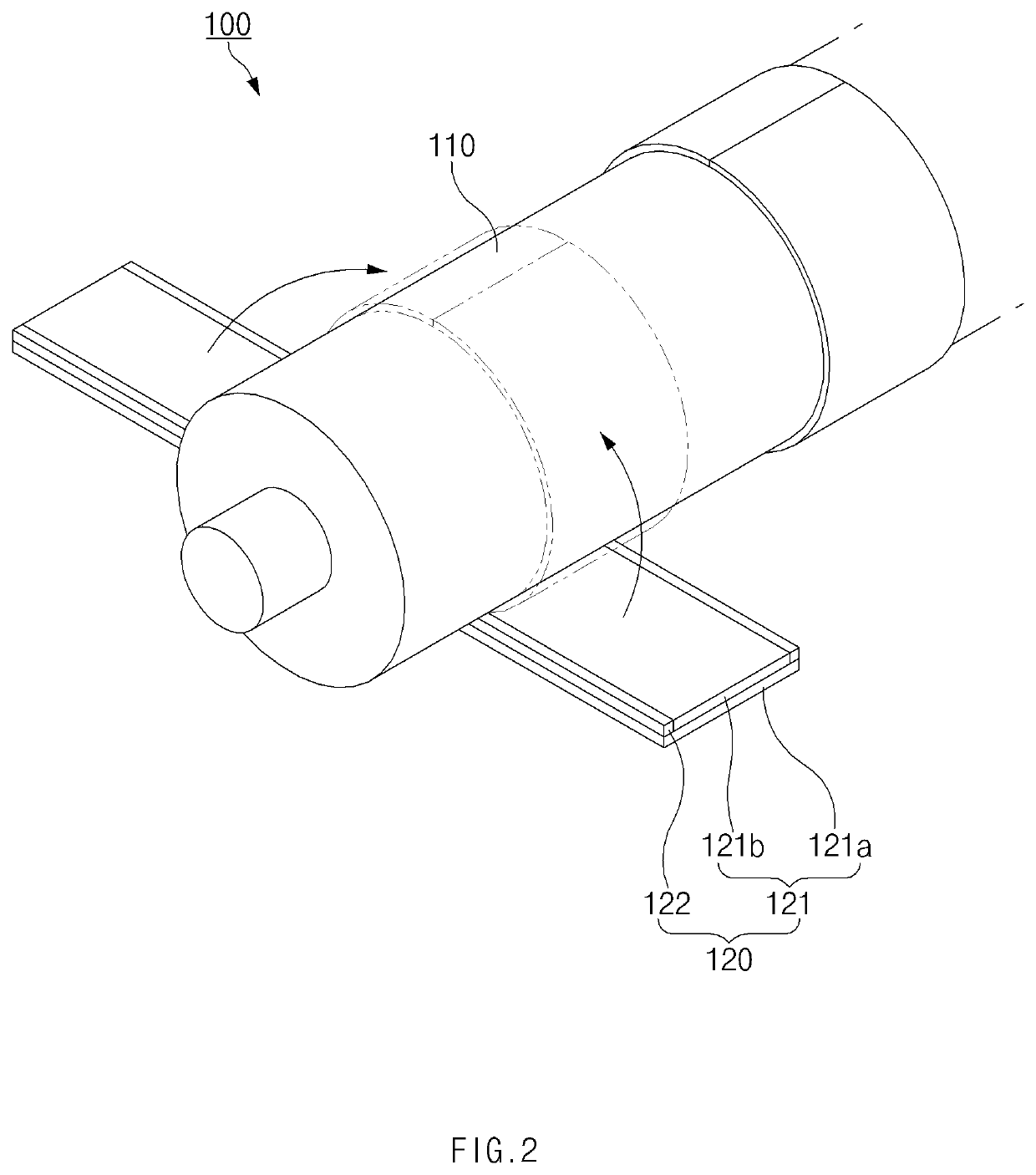
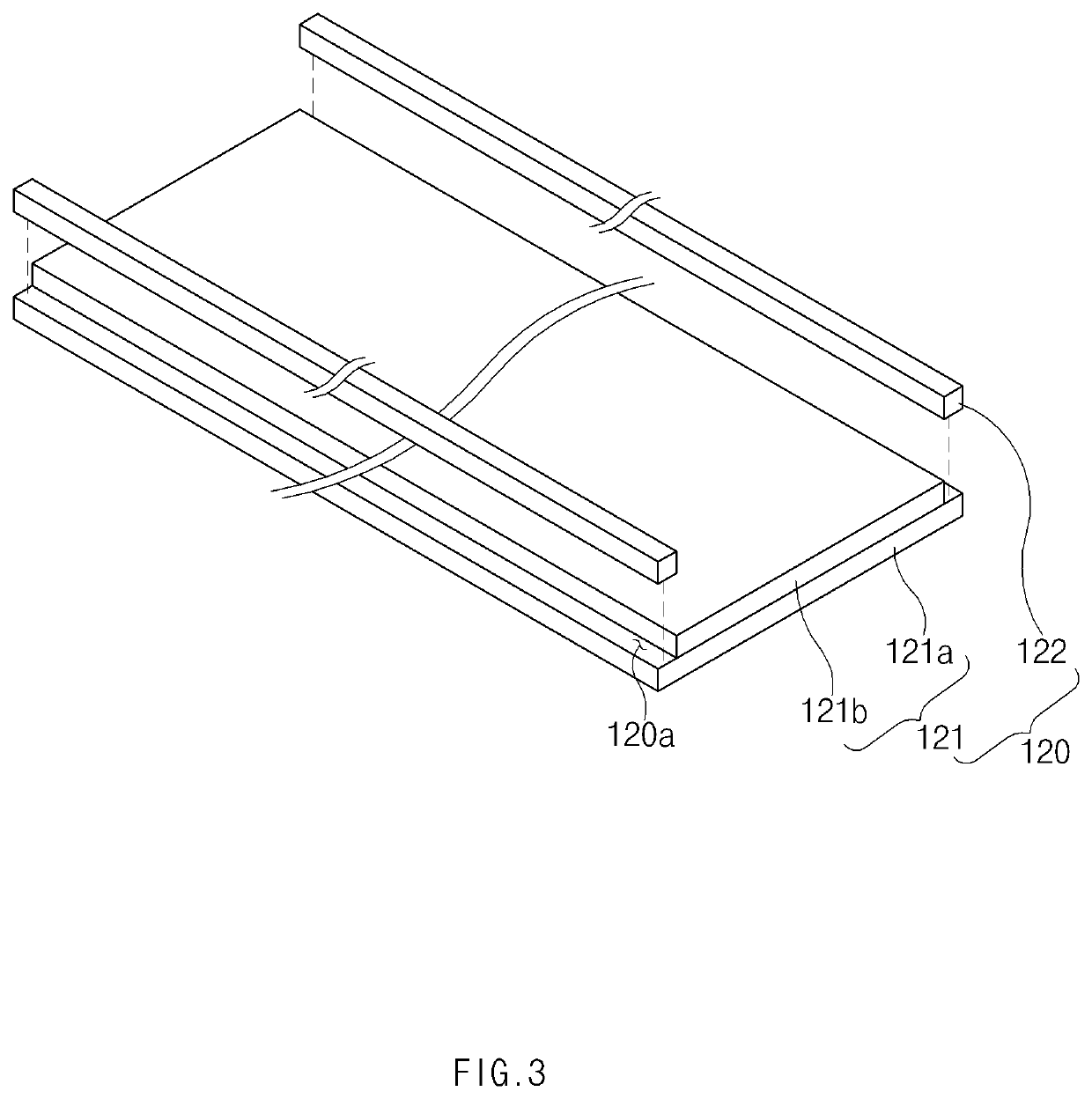
[0036]As illustrated in FIG. 2, the pattern roller part 100 is configured to embody the pattern on the electrode assembly and includes a rotation roller 110 disposed on a surface (a top surface when viewed in FIG. 1) of the electrode assembly 10 to emit heat and ...

second embodiment

Lamination Device of the Present Invention

[0056]FIGS. 5 and 6 are views of a lamination device according to a second embodiment of the present invention.

[0057]As illustrated in FIGS. 5 and 6, a lamination device according to another embodiment of the present invention includes a pattern roller part 100′ including a rotation roller 110′ and a pattern cover 120 wound around the rotation roller 110′.

[0058]Here, the rotation roller 110′ has a support groove 111 along an outer circumferential surface thereof, and the pattern cover 120 is wound around the outer circumferential surface of the rotation roller 110′ along the support groove 111. Thus, the pattern cover 120 may be coupled to the rotation roller 110′ without separate setting-up of a position to improve work's efficiency, thereby preventing the pattern cover 120 from moving in a longitudinal direction of the rotation roller 110′. Here, an adhesion material having adhesion may be applied to or injected between the support groove...


PUM

PropertyMeasurementUnit
temperatureaaaaaaaaaa

Abstract

A lamination device of the present invention includes a pattern roller part embodying a pattern on an electrode assembly, wherein the pattern roller part includes a rotation roller disposed on a surface of the electrode assembly to emit heat and a pattern cover wound around an outer circumferential surface of the rotation roller and partially pressing the surface of the electrode assembly together with the heat transferred from the rotation roller to embody a pattern, and the pattern cover includes a pattern film wound around the outer circumferential surface of the rotation roller and a deformation member disposed on an inner surface of the pattern film to wind the pattern film around the outer circumferential surface of the rotation roller while being deformed by the heat transferred from the rotation roller.

Description

CROSS-REFERENCE TO RELATED APPLICATION[0001]The present application claims the benefit of the priority of Korean Patent Application No. 10-2016-0146929, filed on Nov. 4, 2016, which is hereby incorporated by reference in its entirety.TECHNICAL FIELD[0002]The present invention relates to a lamination device in which a shape-memory alloy is applied to a pattern roller part for embodying a pattern on an electrode assembly.BACKGROUND ART[0003]In general, secondary batteries refer to chargeable and dischargeable batteries, unlike primary batteries that are not chargeable. Such a secondary battery is being widely used in the high-tech electronic fields such as mobile phones, notebook computers, and camcorders.[0004]The secondary battery includes an electrode assembly, an electrolyte, and a case in which the electrode assembly and the electrolyte are accommodated. The electrode assembly is manufactured by alternately stacking a plurality of electrodes and a plurality of separators.[0005]In...

Claims


Application Information

Patent Timeline
Patent Type & Authority Patents(United States)
IPC IPC(8): B32B37/00H01M10/0585H01M4/04H01M10/04
CPCH01M4/0433H01M10/0585H01M4/0435B32B37/0053H01M10/04Y02E60/10Y02P70/50H01M10/0404H01M10/0436H01M10/0468
Inventor KIM, DONG HYUNKIM, KYUNG TAEKKOO, SANG HYUN
Owner LG ENERGY SOLUTION LTD
Learn More