
Antenna device for mobile communication system

a mobile communication system and antenna technology, applied in the direction of antennas, antenna details, radiating element housings, etc., can solve the problems of difficult and costly installation work, unaesthetically pleasing, and material cost and processing cost, so as to reduce installation cost, material cost and manufacturing cost, the effect of minimizing unnecessary expenditur

Active Publication Date: 2020-03-31
KMW INC
View PDF35 Cites 0 Cited by
  • Summary
  • Abstract
  • Description
  • Claims
  • Application Information

AI Technical Summary

Benefits of technology

The antenna device described in this patent reduces installation and material costs by improving the manufacturing method of a service band separator / combiner, which can be added to the antenna. This allows for the production of competitively-priced products that minimize unnecessary expenditure. Additionally, the device reduces external environmental factors like waterproofness and aesthetic issues caused by the provision of the service band separator / combiner.

Problems solved by technology

However, additional production and installation of the service band separator / combiner 16 has a problem of material cost and processing cost for the manufacture of a separate device, and also the installation work is difficult and costly.
Thereby, the installation is likely to raise problems regarding waterproofing of each connection part and produces a result that is not aesthetically pleasing.

Method used


Image

  • Antenna device for mobile communication system
  • Antenna device for mobile communication system
  • Antenna device for mobile communication system

Examples


first embodiment

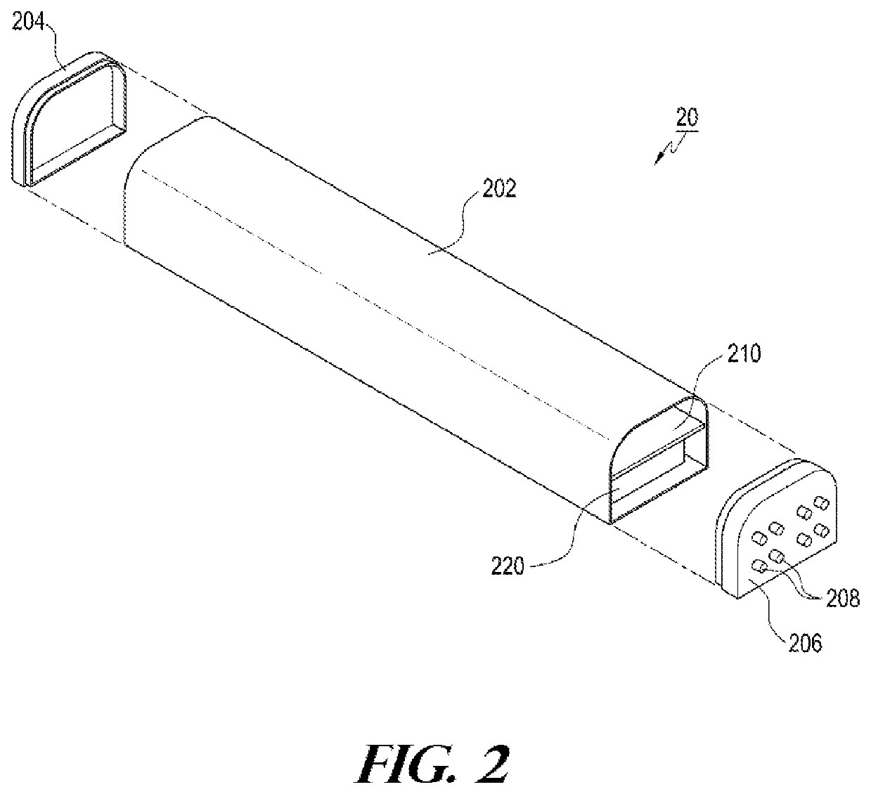
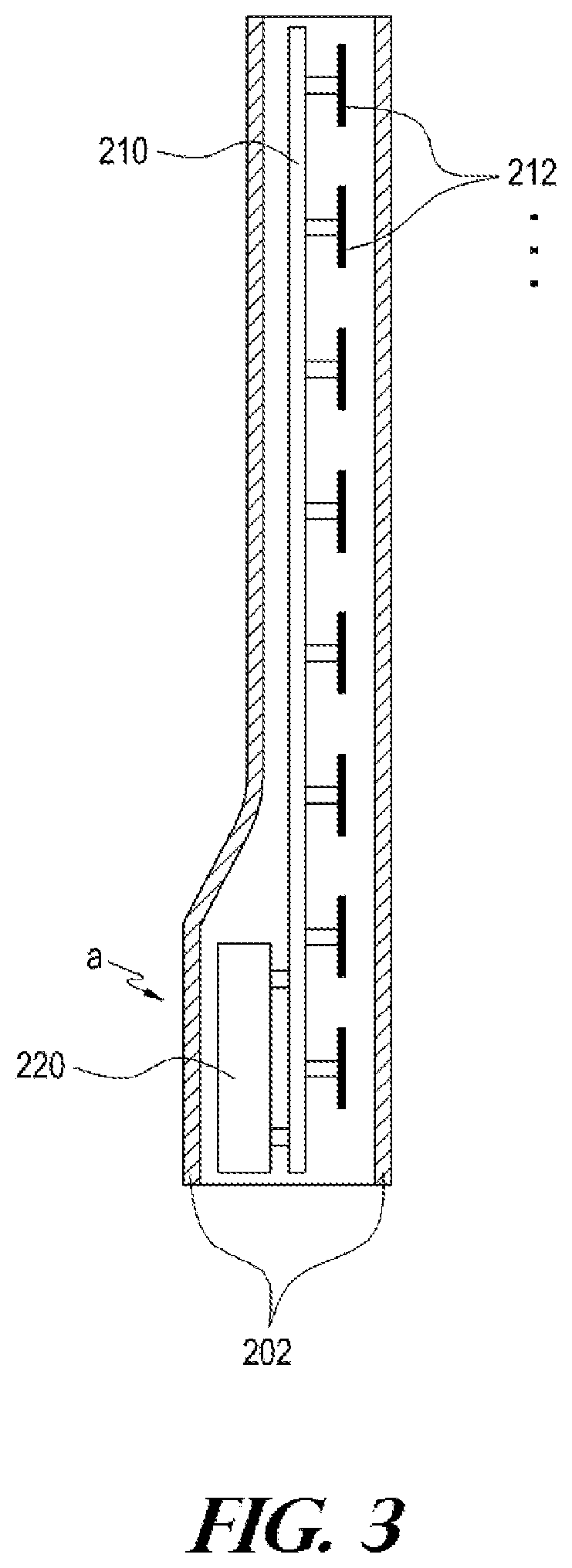
[0022]FIG. 2 is a partially exploded schematic perspective view of an antenna device for a mobile communication system according to the present disclosure. FIG. 3 is a side view of the internal structure of the main parts of FIG. 2. Referring to FIGS. 2 and 3, an antenna device 20 according to an embodiment of the present disclosure is formed in the shape of a metal plate having a relatively large area, and includes a reflector 210 having a plurality of radiating elements 212 for transmitting and receiving a radio signal mounted on one surface (e.g., a front surface) thereof; a service band separator / combiner220 installed at, for example, a lower side on the other surface (for example, a rear surface) of the reflector 210 to separate / combine the service band of the antenna device 20; a radome 202 surrounding the reflector 210 and the service band separator / combiner 220 and formed in the shape of an integrated cylinder; and an upper cap 204 and a lower cap 206 for fixing the upper an...

third embodiment

[0043]Furthermore, the present antenna device 20 employs a multi-antenna structure for providing a multi-service band or a structure for implementing a multi-input multi-output (MIMO) scheme, and thus requires a large number of input / output connectors. However, installing a large number of such input / output connectors on the lower cap 206 or the like causes difficulty in design due to space constraints, and substantially limits the number of installable input / output connectors. In contrast, the structure according to the present disclosure shown in FIG. 7 may solve this problem since the input / output connector 208 can be installed on, for example, the rear surface of the radome 202.

[0044]The configuration and operation of the antenna apparatus for a mobile communication system according to an embodiment of the present disclosure may be implemented as described above. While the present disclosure has been described in connection with what is presently considered to be practical exemp...


PUM


Abstract

The present disclosure relates to an antenna device for a mobile communication system, including a reflection plate, a service band separator / coupler and a radome. The reflection plate is configured in a plate shape, multiple radiation elements being mounted on one surface of the reflection plate so as to transmit / receive radio signals. The service band separator / coupler is installed on the other surface of the reflection plate so as to separate / couple the service band of the corresponding antenna device. The radome is configured in the shape of an integrated barrel that surrounds the reflection plate and the service band separator / coupler as a whole.

Description

CROSS REFERENCE TO RELATED APPLICATIONS[0001]This application is a continuation of an International Application No. PCT / KR2015 / 008980 filed on Aug. 27, 2015, which claims priority to Korean Patent Application No. 20-2014-0006622 filed on Sep. 5, 2014, the entire disclosures of which are incorporated herein by reference.TECHNICAL FIELD[0002]The present disclosure relates to an antenna device applicable to a base station or a relay station in a mobile communication (PCS, cellular, CDMA, GSM, LTE, etc.) network.BACKGROUND[0003]Generally, a base station of a mobile communication system has been divided into a base station main unit configured to process transmit and receive signals and an antenna device including a plurality of radiating elements to transmit / receive radio signals. Usually, the base station main unit is installed at a low position on the ground, and the antenna device is installed at a high position such as a building roof or a tower, and the base station main unit and t...

Claims


Application Information

Patent Timeline
Patent Type & Authority Patents(United States)
IPC IPC(8): H01Q15/14H01Q1/42H01Q1/24H04W88/08
CPCH01Q1/42H01Q15/14H01Q1/246H04W88/08
Inventor SO, SUNG-HWANKANG, SEONG-MANJUNG, EUN-SUKLEE, SANG-HUNPARK, DAE-MYUNG
Owner KMW INC
Learn More