Processes for producing effect layers

a technology of optical effect and process, applied in the direction of magnetic bodies, magnetic paints, magnetic materials, etc., can solve the problems of poor reflection of optical effect layers, undesirable appearance of large dark areas in magnetically transferred images, and optical effect layers that may suffer from low reflectivity and brightness, and achieve reliable and easy-to-implement process. , the effect of easy-to-implemen

Active Publication Date: 2020-04-07
SICPA HLDG SA
View PDF42 Cites 1 Cited by
  • Summary
  • Abstract
  • Description
  • Claims
  • Application Information

AI Technical Summary

Benefits of technology

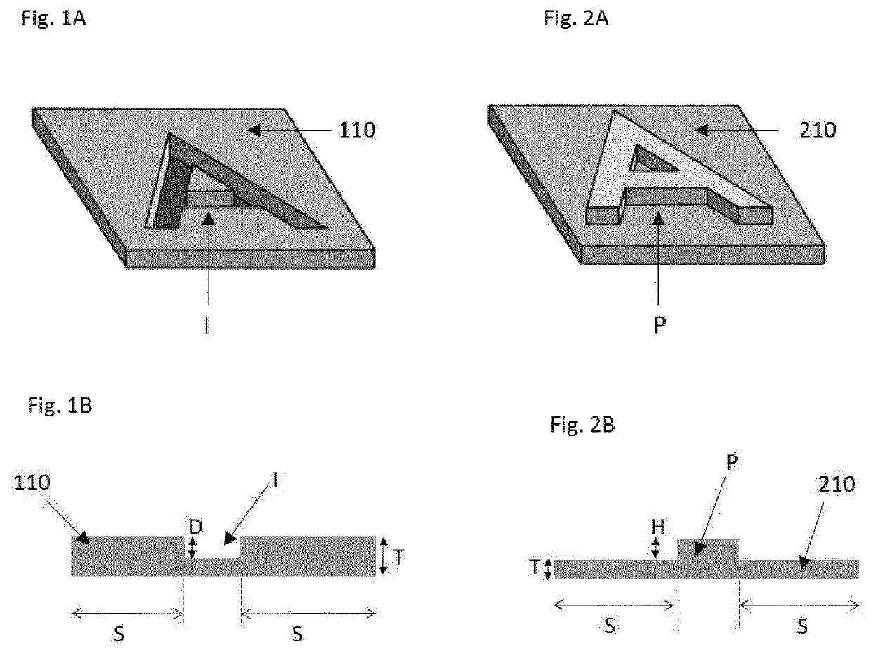
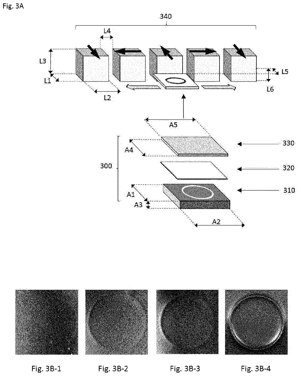
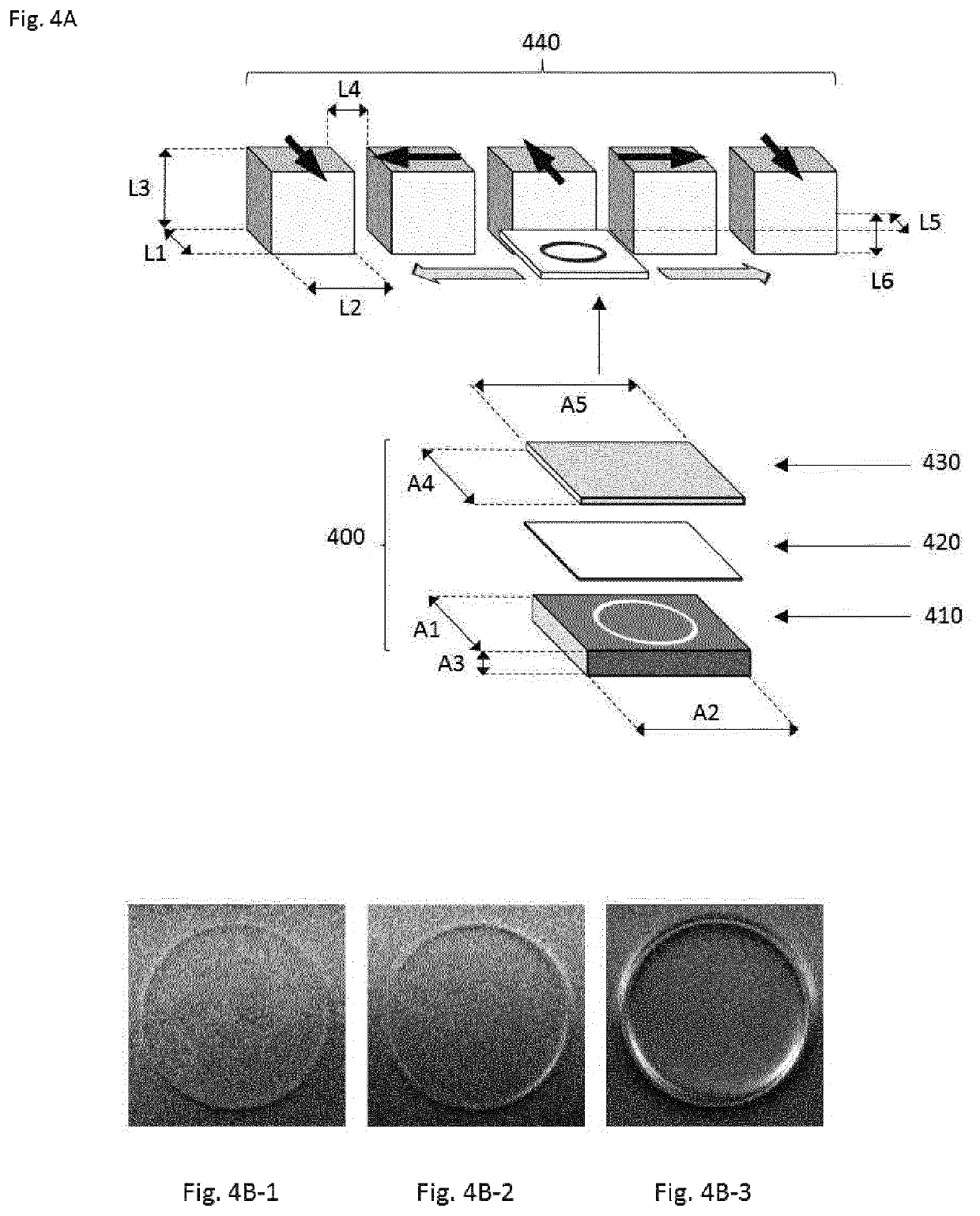
[0018]The present invention provides a reliable and easy to implement process to magnetically transfer one or more indicia into a coating layer formed from a coating composition in a first state, i.e. not yet hardened (i.e. wet) state, wherein the platelet-shaped magnetic or magnetizable pigment particles are free to move and rotate within the binder material so as to form an optical effect layer (OEL) with an eye-catching relief and / or 3D effect after having hardened the coating layer to a second state wherein orientation and position of the platelet-shaped magnetic or magnetizable pigment particles are fixed / frozen. The magnetic transfer of one or more indicia into the coating layer comprising platelet-shaped magnetic or magnetizable pigment particles on the substrate is carried out by forming an assembly comprising the substrate carrying the coating layer and the soft magnetic plate, in particular by placing the substrate carrying the coating layer above (i.e. on top of) the soft magnetic plate carrying one or more indicia in the form of indentations and / or protrusions and moving said assembly through the inhomogeneous magnetic field of a static magnetic-field-generating device. By “inhomogeneous magnetic field”, it is meant that along the path of motion followed by individual platelet-shaped magnetic or magnetizable pigment particles of the coating layer, the magnetic field lines change at least in direction within a plane which is fixed in the reference frame of the moving assembly. In this way, at least a part of the platelet-shaped magnetic or magnetizable pigment particles of the coating layer tend to align within said plane, resulting in a bi-axial orientation of said platelet-shaped magnetic or magnetizable particles, i.e. an orientation in which the two largest principal axes of said platelet-shaped pigment particles are constrained. During this bi-axial orientation, the one or more indentations and / or protrusions affect the direction and / or intensity of the magnetic field generated by the static magnetic-field-generating device, thus affecting the orientation of the platelet-shaped magnetic or magnetizable pigment particles placed just above or below said one or more indicia so as to produce the desired eye-catching relief and / or 3D effect. In a preferred embodiment, the plane described herein is parallel or substantially parallel to the plane of the OEL in the one or more areas which are not directly above or below said one or more indicia, resulting in an orientation of at least a part of the platelet-shaped magnetic or magnetizable pigment particles that is parallel or substantially parallel to the substrate carrying the OEL. In another embodiment, the magnetic field along the path of motion vary within a plane or planes that form a non-zero angle with respect to the plane of the OEL, resulting in an orientation of at least a part of the platelet-shaped magnetic or magnetizable pigment particles which is essentially non-parallel to the substrate carrying the OEL. Once the desired effect is created in the not yet hardened (i.e. wet) coating layer, the coating composition is partly or completely hardened so as to permanently fix / freeze the relative position and orientation of the platelet-shaped magnetic or magnetizable pigment particles in the OEL.
[0019]Moreover, the process provided by the present invention is mechanically robust, easy to implement with an industrial high-speed printing equipment, without resorting to cumbersome, tedious and expensive modifications of said equipment.

Problems solved by technology

The protection provided by covert security features relies on the principle that such features are difficult to detect, typically requiring specialized equipment and knowledge for detection, whereas “overt” security features rely on the concept of being easily detectable with the unaided human senses, e.g. such features may be visible and / or detectable via the tactile sense while still being difficult to produce and / or to copy.
However, and as described in EP 1 937 415 B1, the devices disclosed in EP 1 641 624 B1 may result in poorly reflecting optical effect layers having a rather dark visual appearance.
The disclosed drawback of EP 1 641 624 B1 results from the mainly perpendicular orientation of the magnetic pigment particles with respect to the printed substrate plane over a large part of the oriented coating layer, as resulting from the perpendicular magnetization which is required in said device.
The disclosed device may still lead to the undesirable appearance of large dark areas in the magnetically transferred image, in particular in zones where the magnetic field lines are substantially perpendicular to the substrate surface.
Accordingly, a sole mono-axial orientation of magnetic pigment particles results in optical effect layers that may suffer from a low reflectivity and brightness as light is reflected in a wide range of directions, especially in directions that are substantially perpendicular to the magnetic field lines.
A drawback of the disclosed devices resides in the galvanization process since said process is cumbersome and needs special equipments.
This is particularly cumbersome from an industrial point of view as it requires complex mechanical systems.
Such orientations are not well suited to clearly reveal indicia with an eye-catching relief / 3D effect, as the sphere-like effect is superimposed with the indicia.
The only method that can be derived from the description to generate relatively flat rotating fields would be to rotate very large magnets, which is impractical.
Whereas the method disclosed in WO 2015 / 086257 A1 allows the production of optical effects layers exhibiting improved brightness and contrast compared to the prior art, the so-obtained optical effects layers may still suffer from a poorly reflecting visual appearance and does not teach how to impart an appealing 3D / relief impression to the indicia.

Method used


Image

  • Processes for producing effect layers
  • Processes for producing effect layers
  • Processes for producing effect layers

Examples


examples

[0142]A black commercial paper (Gascogne Laminates M-cote 120) was used as substrate (x20) for the examples described hereafter.

[0143]The UV-curable screen printing ink described in Table 1 was used as a coating composition comprising platelet-shaped optically variable magnetic pigment particles so as to form a coating layer (x30). The coating composition was applied on the substrate (x20), said application being carried out by hand screen printing using a T90 screen so as to form a coating layer (x30) having a thickness of about 20 μm.

[0144]

TABLE 1Epoxyacrylate oligomer36% Trimethylolpropane triacrylate monomer13.5%  Tripropyleneglycol diacrylate monomer20% Genorad ™ 16 (Rahn)1%Aerosil ® 200 (Evonik)1%Speedcure TPO-L (Lambson)2%IRGACURE ® 500 (BASF)6%Genocure EPD (Rahn)2%Tego ® Foamex N (Evonik)2%Plateleted-shaped optically variable16.5%  magnetic pigment particles (7 layers)(*)(*)gold-to-green optically variable magnetic pigment particles having a flake shape of diameter d50 about...


PUM

PropertyMeasurementUnit
pressureaaaaaaaaaa
wavelength rangeaaaaaaaaaa

Abstract

The invention relates to the field of the protection of security documents such as for example banknotes and identity documents against counterfeit and illegal reproduction. In particular, the present invention provides processes for magnetically transferring one or more indicia into a not yet hardened coating layer made of a coating composition comprising platelet-shaped magnetic or magnetizable pigment particles so as to produce optical effect layers (OELs) as anti-counterfeit means on security documents or security articles or for decorative purposes.

Description

FIELD OF THE INVENTION[0001]The present invention relates to the field of processes for producing optical effect layers (OELs) comprising magnetically oriented platelet-shaped magnetic or magnetizable pigment particles. In particular, the present invention provides processes for magnetically transferring one or more indicia into coating layers comprising platelet-shaped magnetic or magnetizable pigment particles so as to produce OELs and the use of said OELs as anti-counterfeit means on security documents or security articles as well as decorative purposes.BACKGROUND OF THE INVENTION[0002]It is known in the art to use inks, compositions, coatings or layers containing oriented magnetic or magnetizable pigment particles, particularly also optically variable magnetic or magnetizable pigment particles, for the production of security elements, e.g. in the field of security documents. Coatings or layers comprising oriented magnetic or magnetizable pigment particles are disclosed for examp...

Claims


Application Information

Patent Timeline
Patent Type & Authority Patents(United States)
IPC IPC(8): B05D5/06B42D25/369H01F1/20B42D25/29B05D3/00
CPCB05D5/065B42D25/369B42D25/29B05D3/207B42D25/378B42D25/45C09D7/61B05D7/24C09D5/23H01F1/147H01F1/20B05D3/00B44F1/08
Inventor NIKSERESHT GHANEPOUR, NEDALOGINOV, EVGENYSCHMID, MATHIEUDESPLAND, CLAUDE-ALAINMULLER, EDGAR
Owner SICPA HLDG SA
Why Eureka
Try Eureka